Semiconductor device including a coupling conductor having a concave and convex
a technology of concave and convex conductors and semiconductor devices, which is applied in the direction of semiconductor devices, semiconductor/solid-state device details, electrical apparatus, etc., can solve the problems of inability to utilize aluminium, complex assembling steps, and high cost, so as to achieve high thermal conductivity, simple assembling steps, and high electric conductivity
- Summary
- Abstract
- Description
- Claims
- Application Information
AI Technical Summary
Benefits of technology
Problems solved by technology
Method used
Image
Examples
embodiment mode 1
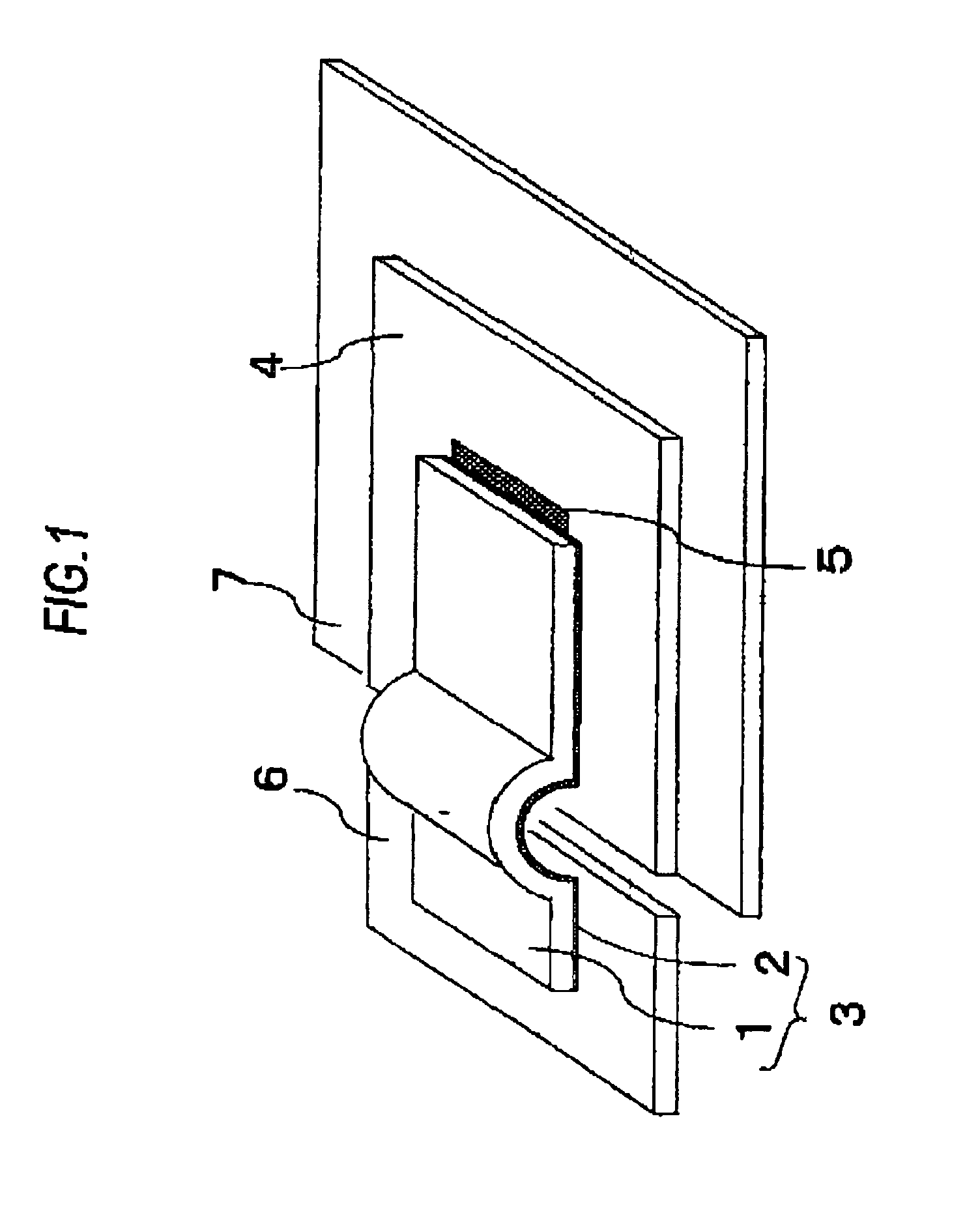
[0040]FIG. 1 is a perspective view for indicating a semiconductor device according to an embodiment mode 1 of the present invention. In FIG. 1, while a semiconductor element 4 has been electrically connected via a coupling conductor 3 to one end of a lead 6 of a lead frame, a first conductor 1 is a plate-shaped conductor that contains copper as a major component, and a second conductor 2 is an aluminium layer. The aluminium layer is employed in order to electrically connect an element electrode 5 formed on the semiconductor element 4 to the lead 6 of the lead frame. This coupling conductor 3 has been manufactured by stacking the second conductor 2 on one plane of the first conductor 1, and, in FIG. 1, has been formed in a layer shape in such a manner that the first conductor 1 may be electrically connected on the second conductor 2. Although a plane of the second conductor 2 provided on the side to be electrically connected to the lead 6 is plain, concave / convex portions may be alte...
embodiment mode 2
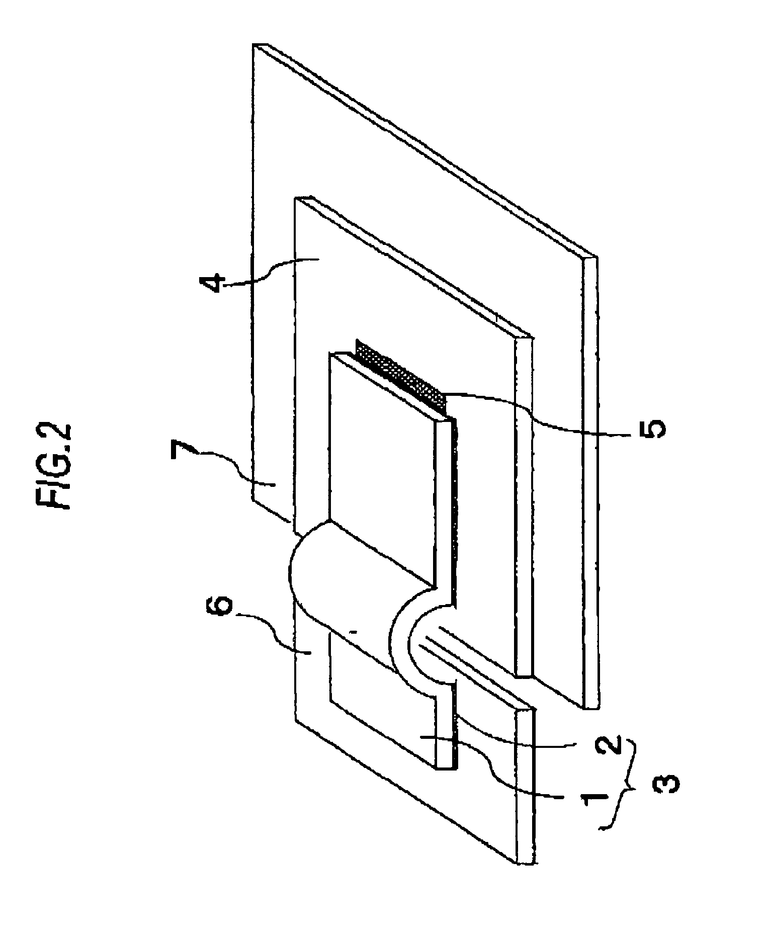
[0048]FIG. 2 is a schematic diagram of a semiconductor device according to an embodiment mode 2 of the present invention. A structural difference from that of the above-described embodiment mode 1 is given as follows: That is, a second conductor 2 constructed of an aluminium layer has been provided with respect only to such a region which is electrically connected to both an element electrode 5 and a lead 6 by performing an ultrasonic connecting method. It should be understood that in the below-mentioned embodiment mode 2, the same reference numerals will be employed as those for denoting the same structural elements explained in the embodiment mode 1, and detailed descriptions thereof will be omitted.
[0049]In accordance with the above-described structure, in addition to the operation effects achieved by the above-described embodiment mode 1, since a portion that becomes a curved shape is a layer structure of a first conductor 1, a mechanical strength can be maintained, while stripp...
embodiment mode 3
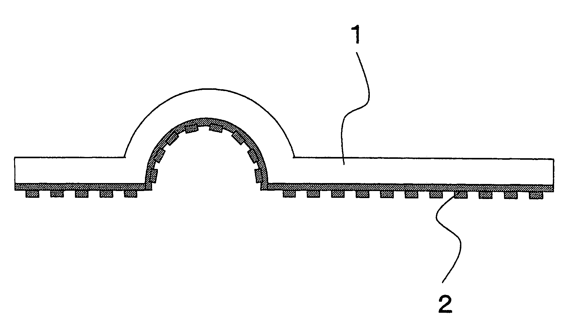
[0053]FIG. 3 is a schematic diagram of a coupling conductor that is employed in order to mount a semiconductor device according to an embodiment mode 3 of the present invention. It should be understood that in the below-mentioned embodiment mode 3, the same reference numerals will be employed as those for denoting the same structural elements explained in the embodiment mode 1, and detailed descriptions thereof will be omitted.
[0054]In FIG. 3, a second conductor 2 has been formed by such a conductor having a plate shape made of combining concaves / convexes, curved planes, and flat planes with each other. FIG. 4 is a plan view of the above-described second conductor 2, as viewed from the side for forming the second conductor 2. In this embodiment mode 3, more specifically, the plate-shaped conductor having the concave / convex shape is employed in such a region which the second conductor 2, the element electrode 5, and the lead 6 are electrically connected. As a result, a close adhesive...
PUM
 Abstract
Description
Claims
Application Information
 - R&D
- Intellectual Property
- Life Sciences
- Materials
- Tech Scout
- Unparalleled Data Quality
- Higher Quality Content
- 60% Fewer Hallucinations
Browse by: Latest US Patents, China's latest patents, Technical Efficacy Thesaurus, Application Domain, Technology Topic, Popular Technical Reports.
© 2025 PatSnap. All rights reserved.Legal|Privacy policy|Modern Slavery Act Transparency Statement|Sitemap|About US| Contact US: help@patsnap.com


