Flooded type evaporating heat-exchange copper tube for an electrical refrigeration unit

a heat exchange tube and copper tube technology, applied in tubular elements, corrosion prevention, coatings, etc., can solve the problems of slow heat transfer rate, large bubble size needed to overcome surface tension, and inability to quickly transfer heat, etc., to speed up the vaporization process, increase the number of vaporization nuclei, and facilitate the formation of nuclei.

Active Publication Date: 2010-11-30
GOLDEN DRAGON PRECISE COPPER TUBE GROUP
View PDF15 Cites 7 Cited by
  • Summary
  • Abstract
  • Description
  • Claims
  • Application Information

AI Technical Summary

Benefits of technology

[0004]An object of the present invention is to provide an evaporating heat-exchange tube with high efficiency.
[0015]The present is advantageous over the prior art as following: (1) Plurality of fifth fins arranged in the primary evaporating chamber divide the evaporating chamber into several minor cavities. Nucleus boiling is easily developed in a refrigerant film on the bottom wall of the minor cavity. Thereafter, the refrigerant film boils and evaporates to form bubbles to escape via evaporating openings. Afterwards, surrounding refrigerant refills the empty minor cavities via the evaporating opening. This process of boiling, evaporation and refilling continues to go on. Thus, due to the configuration of a primary evaporating chamber with plurality of minor cavities, the number of vaporization nucleus is dramatically increased, and the refrigerant is much easier to form nucleus and get vaporized, thus speeding up the vaporization process. (2) Secondary grooves, third grooves, and fourth grooves according to the invention may further disturb the flow as well as provide more channels, through which bubbles may escape and refrigerant may fill in, to further improve the refrigeration property. (3) Inner teeth, with an appropriate number and with a substantially triangular configuration, are provided on the evaporating heat-exchange tube according to the present invention. Therefore, the heat transfer area within the tube is increased and a secondary turbulent flow for the heat-exchange water within the tube is developed, such that the heat transfer efficiency in the tube is dramatically increase. (4) The transitional length L between the smooth surface portion and the finned portion according to the invention is relatively small (5 to 25 mm). Therefore, the number of incomplete fins is reduced, which corresponds to an increase in the heat transfer area. Therefore, the utilization ratio is increased, thus improving the heat transfer efficiency. (5) Inner teeth on the inner surface of the evaporating heat-exchange tube as well as evaporating chamber on the outer surface thereof is employed to improve the heat transfer property within as well as outside of the tube. Meanwhile, the wall thickness and outer diameter of the tube are so well designed that the overall heat transfer coefficient of the copper tube is greatly improved, thus further improving the overall heat transfer property of the evaporator.

Problems solved by technology

However, adding fins on the outer surface may lead to such a disadvantage that thermal resistance will be developed between the fins and the tube, while heat-exchange fins forming directly on the outer surface are often limited by the machining process and the size of the tube, such that a requirement to transfer heat rapidly may not be well met.
Therefore, the bubble size needed to overcome the surface tension is also quite large, and the rate of the heat transfer is slowed sown.
Meanwhile, this also slows down the formation rate of new bubbles.
The longer this transitional length is, the more will be incomplete fins, and the more will the refrigeration property be adversely affected.

Method used


Image

  • Flooded type evaporating heat-exchange copper tube for an electrical refrigeration unit
  • Flooded type evaporating heat-exchange copper tube for an electrical refrigeration unit
  • Flooded type evaporating heat-exchange copper tube for an electrical refrigeration unit

Examples


Embodiment Construction

[0021]A preferred embodiment of the present invention will be described in more details with reference to accompany drawings.

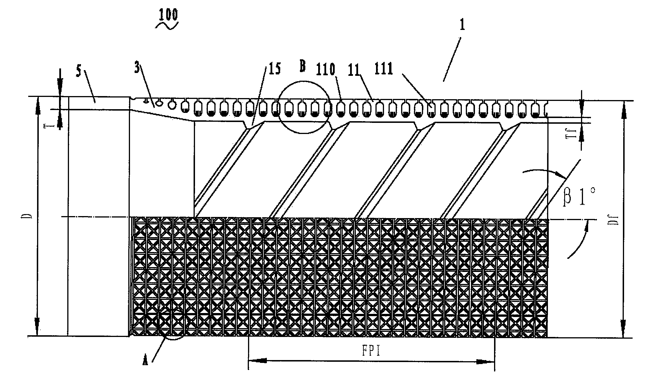
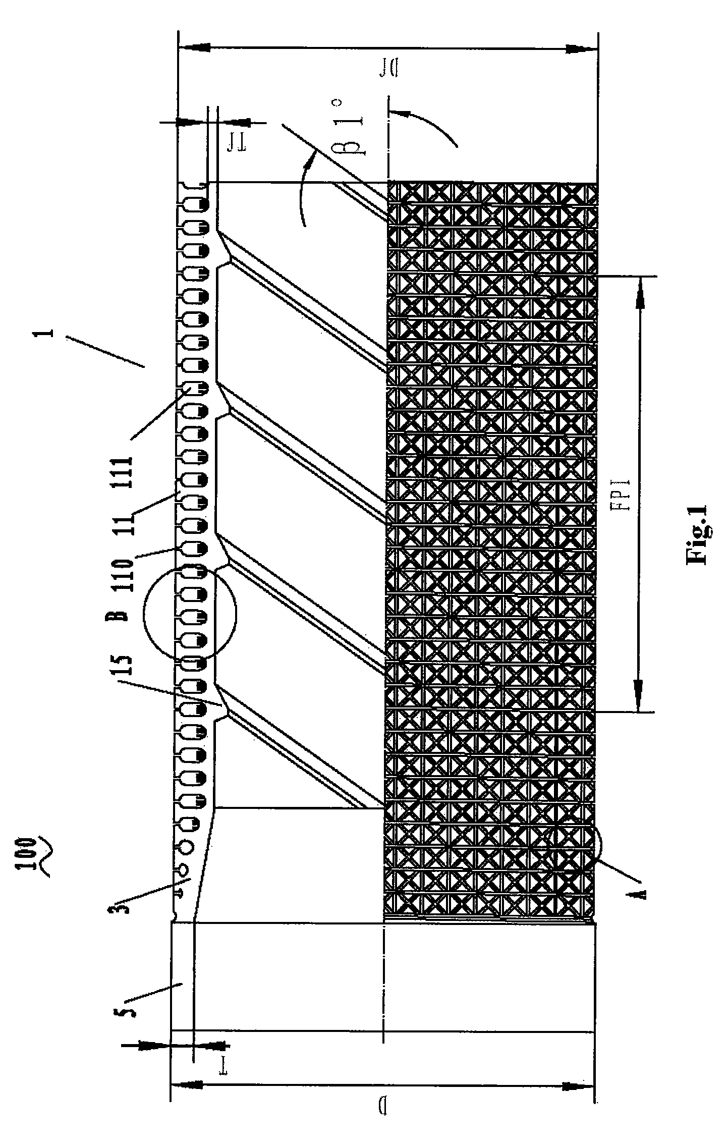
[0022]Referring to FIG. 1, an evaporating heat-exchange tube 100 according to the present invention comprises a finned portion 1, smooth surface portions 5 arranged at both ends of the evaporating heat-exchange tube 100 (only one shown in FIG. 1), a transitional portion 3 arranged between the smooth surface portion 5 and the finned portion 1, and inner teeth 15 arranged inside the evaporating heat-exchange tube 100. The outer diameter D for the smooth surface portion 5 is between 12 and 26 mm, while the wall thickness T thereof is between 0.5 and 0.9 mm. The evaporating heat-exchange tube 100 according to the present invention is preferably made of copper material. After studying the heat-transfer mechanism, molding device, and molding process of a flooded type evaporating heat-exchange tube, the applicant chooses a range between 12 and 26 mm for the diameter ...


PUM

PropertyMeasurementUnit
widthaaaaaaaaaa
widthaaaaaaaaaa
widthaaaaaaaaaa

Abstract

The present invention discloses a flooded type evaporating heat-exchange copper tube for an electrical refrigeration unit. The evaporating heat-exchange tube comprises a smooth surface portion, a finned portion provided with plurality of fins and a transitional portion connecting the smooth surface portion to the finned portion, with primary evaporating chambers defined between the fins. Fifth fins extending upwardly are provided on a bottom wall of the primary evaporating chamber, which divide the primary evaporating chamber into at least two minor cavities, and an evaporating opening is defined between adjacent fins of the primary evaporating chamber. Due to plurality of minor cavities arranged in the evaporating heat-exchange tube, refrigerant film is easy to form on bottom walls of the minor cavities, and nucleus boiling is easily to be developed. Thereafter, the refrigerant gets boiled and evaporated to form bubbles to escape via evaporating openings. Surrounding refrigerant refills the empty minor cavities via the evaporating opening. This process of boiling, evaporation and refilling continues to go on. Thus, the number of vaporization nucleus is dramatically increased, and the refrigerant is much easier to form nucleus and get vaporized, thus improving the heat transfer property of the evaporating heat-exchange tube.

Description

RELATED APPLICATION[0001]This application claims priority under 35 U.S.C. 119 to Chinese Patent Application Serial No. 200510134630.9, filed Dec. 13, 2005, which application is incorporated herein by reference and made a part hereof.TECHNICAL FIELD[0002]The present invention relates to an evaporating heat-exchange tube, especially to a flooded type evaporating heat-exchange copper tube for an electrical refrigeration unit.BACKGROUND[0003]In recent years, the development of the manufacturing technology for a refrigerator or an air conditioner has been advanced due to a rapid development in the refrigeration technique and air-conditioning technique. Most effort is concentrated on providing a refrigerator or air conditioner with higher efficiency, less volume and lower weight, as well as an improved refrigerant. Meanwhile, the design and technical application for an evaporating heat-exchange tube used in the refrigerator or air conditioner has also been continuously improved. Currently...

Claims


Application Information

Patent Timeline
Patent Type & Authority Patents(United States)
IPC IPC(8): F28F13/18
CPCF28F1/38F28F13/187F28F1/40Y10T29/49391
Inventor HAO, YUNYUJIANG, QIANGYU, CHUANFUZHAO, SHUANG
Owner GOLDEN DRAGON PRECISE COPPER TUBE GROUP
Why Eureka
Try Eureka