
Sensing system

a sensing system and sensor technology, applied in the field of sensing systems, can solve the problems of difficult high-precision analysis using local plasmon sensors, high cost of surface plasmon sensors, and severe structural constraints, and achieve the effect of simple construction and satisfying detection sensitivity

Inactive Publication Date: 2010-11-30
FUJIFILM CORP
View PDF35 Cites 6 Cited by
  • Summary
  • Abstract
  • Description
  • Claims
  • Application Information

AI Technical Summary

Benefits of technology

The present invention provides a sensing system that uses a sensing element with improved detection sensitivity and a simpler construction than surface plasmon sensors. The sensing element includes a transparent body, two reflectors that vary with the physical characteristics of the specimen, and an absorption characteristic that reflects the wavelength of light injected onto the sensing element. The sensing system also includes a light injection unit that injects light with two or more wavelengths onto the sensing element, and a calculation unit that obtains a difference between the intensity of light from the first and second reflectors. The sensing system may have additional features such as protrusions and recesses, metal layers, or micropores in the transparent body. The use of laser light and a semiconductor laser can further reduce the size and weight of the sensing system.

Problems solved by technology

However, since the above surface plasmon sensor uses the prismatic dielectric block, the cost of the surface plasmon sensor is high, and the surface plasmon sensor has severe structural constraints on downsizing or adaptation to concurrent analysis of a number of specimens.
However, the detection sensitivity of the local plasmon sensor is poor compared with the surface plasmon sensor, so that it is difficult to perform high-precision analysis by using the local plasmon sensor.

Method used


Image

  • Sensing system
  • Sensing system
  • Sensing system

Examples


first embodiment

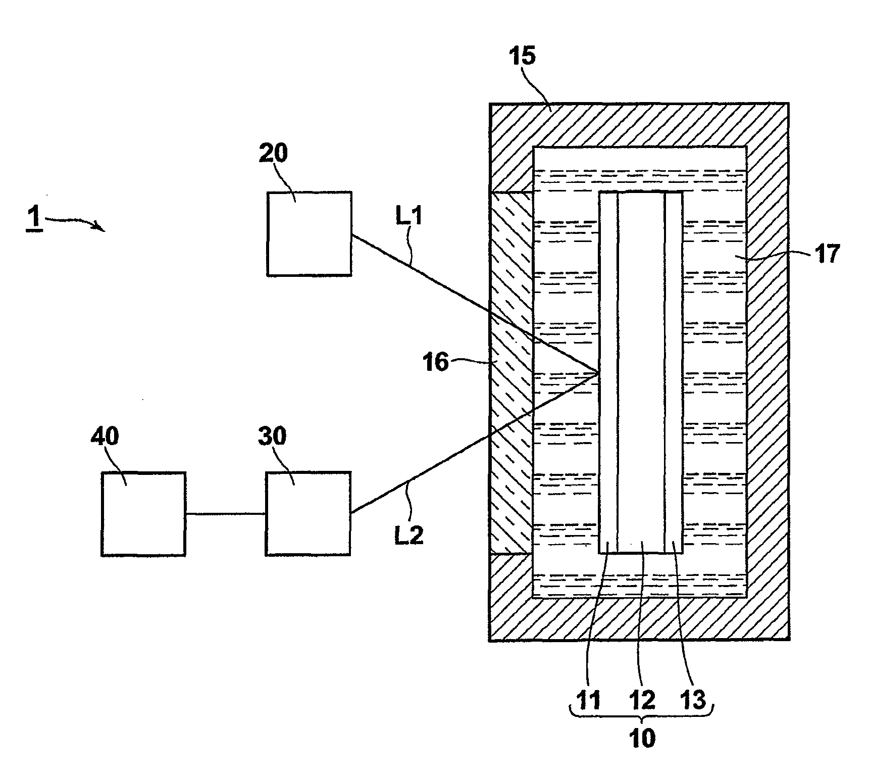
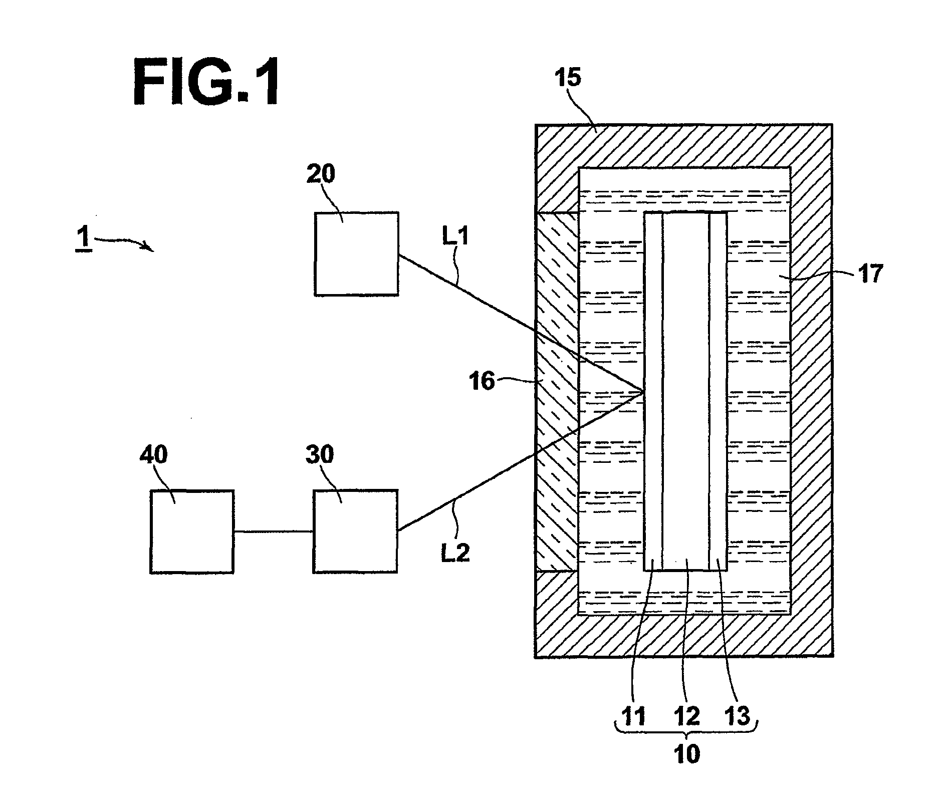
[0062]FIG. 1 is a plan view of a sensing system 1 according to a first embodiment of the present invention. The sensing system 1 comprises a sensing element 10, a specimen cell 15, a light injection unit 20, a light detection unit 30, and a data processing unit 40.

[0063]When light L1 for measurement (hereinafter referred to as measurement light L1) is injected onto the sensing element 10, the sensing element 10 outputs output light L2 having a physical characteristic which depends on a specimen 17. The specimen cell 15 contains the sensing element 10 and the specimen 17, and the light injection unit 20 injects the measurement light L1 onto the sensing element 10. The light detection unit 30 detects the physical characteristic of the output light L2, and outputs a signal representing the detection result. The data processing unit 40 performs analysis of the specimen 17 on the basis of the signal outputted from the light detection unit 30.

[0064]First, the sensing element 10 is explain...

second embodiment

[0104]A sensing system according to the second embodiment of the present invention is explained below with reference to FIG. 4, which is a schematic diagram illustrating a light injection unit 20-1 used in the sensing system according to the second embodiment.

[0105]The light injection unit 20-1 illustrated in FIG. 4 is different from the light injection unit 20 illustrated in FIG. 3 in that the beam splitter 132 and the reflective grating 133 in FIG. 3 are replaced with a partially-reflective grating 134 in FIG. 4. The wavelength stabilizing arrangement 130A in the light injection unit 20-1 is realized by the partially-reflective grating 134. The partially-reflective grating 134 is arranged in the optical path of the measurement light L1 directed to the sensing element 10, and reflects a portion of the measurement light L1. The reflected measurement light L1 is fed back to the semiconductor laser 100 through the half-wavelength plate 131, so that the oscillation wavelength of the se...

third embodiment

[0106]A sensing system according to the third embodiment of the present invention is explained below with reference to FIG. 5, which is a schematic diagram illustrating a light injection unit 20-2 used in the sensing system according to the third embodiment.

[0107]In the light injection unit 20-2 illustrated in FIG. 5, a reflective grating 133 and a collimator lens 135 are arranged on the backward side of the semiconductor laser 100, and the collimator lens 120 and the half-wavelength plate 131 are arranged on the forward side of the semiconductor laser 100, so that an optical feedback system realizing a wavelength selection arrangement 130B is formed. The wavelength stabilizing arrangement 130B in the light injection unit 20-2 is realized by the reflective grating 133 and the collimator lens 135. That is, the light emitted backward from the semiconductor laser 100 (backward emission light L1Q) is collimated by the collimator lens 135 and is then incident on the reflective grating 13...


PUM

PropertyMeasurementUnit
widthaaaaaaaaaa
widthaaaaaaaaaa
dielectric constantaaaaaaaaaa

Abstract

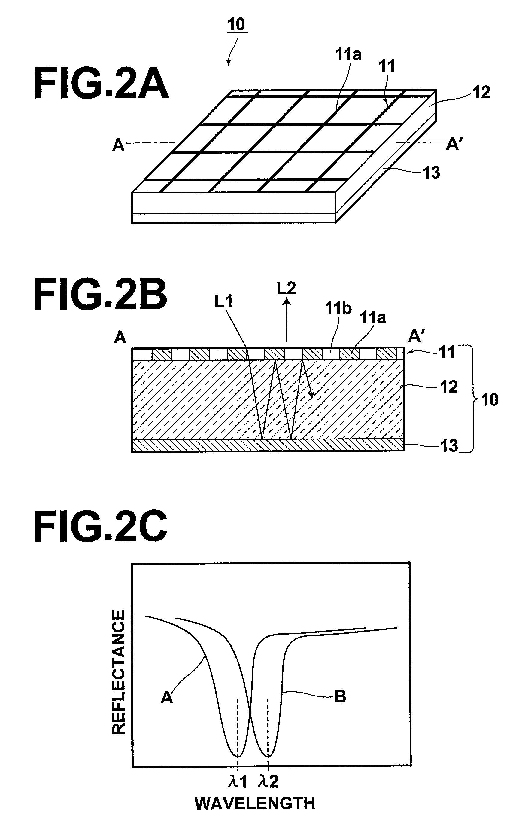
A sensing system using a sensing element being constituted by a transparent body sandwiched by first and second reflectors one or each of which is in contact with a specimen, and exhibiting an absorption characteristic varying with the specimen. The first reflector is a partially transparent reflective, and the second reflector is completely reflective, or partially transparent reflective. A light injection unit injects light onto the first reflector, and a light detection unit detects the intensity of light outputted from the sensing element in response to the injection. The light injection unit has a wavelength stabilizing arrangement and injects laser light, or injects light at two wavelengths. In the latter case, the light detection unit detects the intensities of outputted light at the two wavelengths, and a calculation unit obtains the difference between the intensities.

Description

TECHNICAL FIELD[0001]The present invention relates to a sensing system for analyzing a specimen by use of a sensing element, and detecting light outputted from the sensing element in response to injection of light for measurement, where the light outputted from the sensing element has a physical characteristic which varies with a specimen.BACKGROUND ART[0002]Conventionally, sensors utilizing the phenomenon in which the surface plasmon resonance decreases the intensity of reflected light having a specific wavelength have been proposed for use in analysis of biomolecules and the like, and for example, a surface plasmon sensor having as essential constituents a prismatic dielectric block and a metal film which is formed on the dielectric block and is to be arranged in contact with a specimen has been disclosed in, for example, Japanese Unexamined Patent Publication No. 6 (1994)-167443. In such a surface plasmon sensor, a total reflection condition is satisfied at the interface between ...

Claims


Application Information

Patent Timeline
Patent Type & Authority Patents(United States)
IPC IPC(8): G01N21/55G01N21/43G01N21/00G01B9/02
CPCG01N21/41G01N21/553
Inventor NAYA, MASAYUKIHATORI, MASAMI
Owner FUJIFILM CORP
Learn More