Vibrating element, vibrator, and electronic apparatus
a technology of vibrating element and electronic apparatus, which is applied in the direction of turn-sensitive devices, instruments, and device material selection, etc., can solve the problems of increasing the size of the vibrating element, difficulty in achieving high sensitivity, and arm collision, and achieve satisfactory detection sensitivity
- Summary
- Abstract
- Description
- Claims
- Application Information
AI Technical Summary
Benefits of technology
Problems solved by technology
Method used
Image
Examples
first embodiment
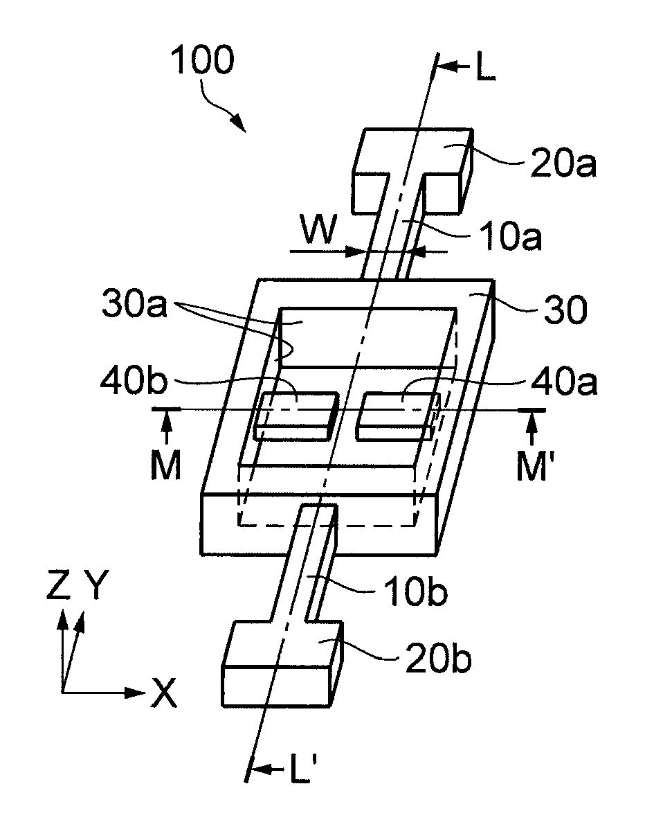
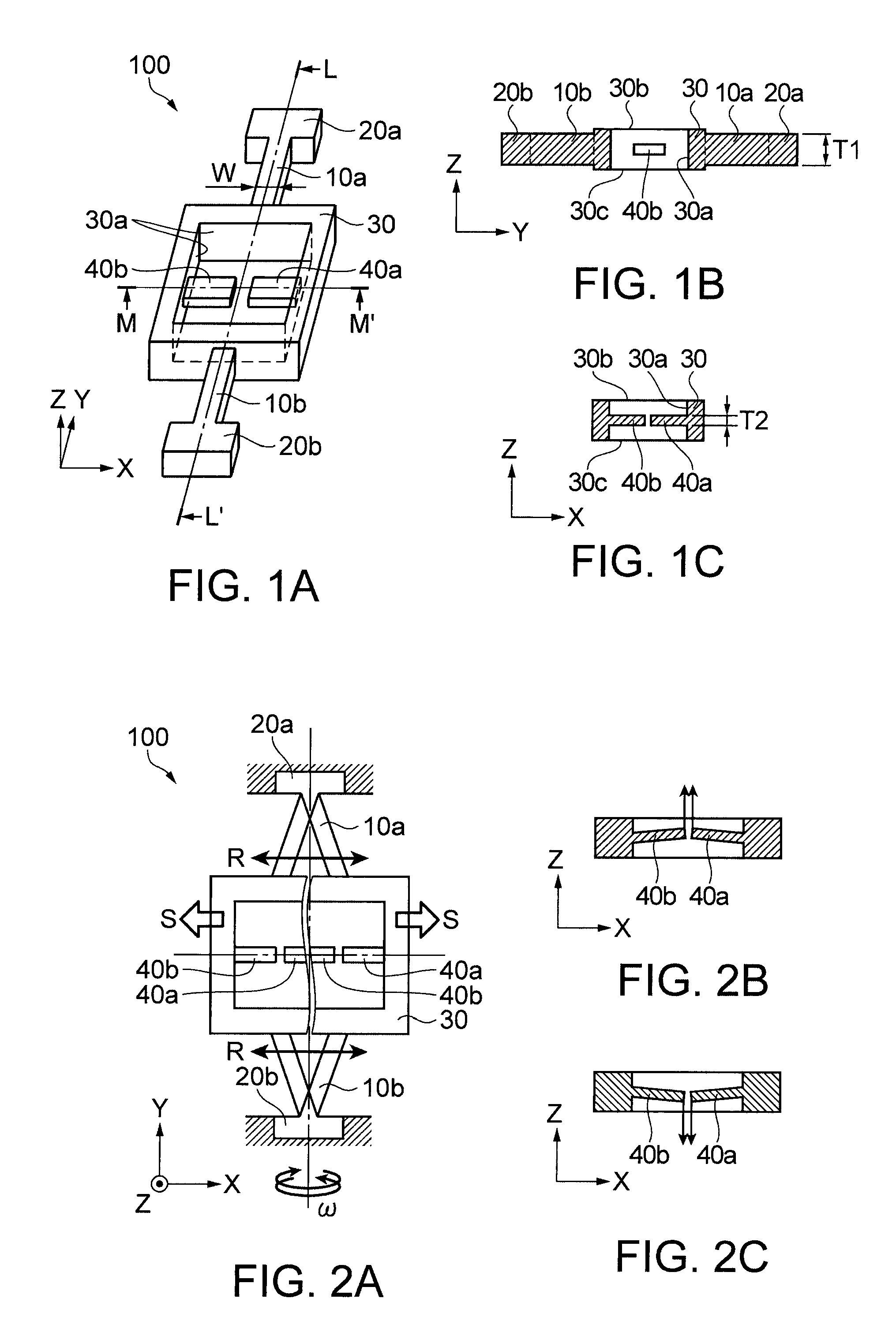
[0045]FIGS. 1A to 1C show a vibrating element of this embodiment. Specifically, FIG. 1A is a schematic perspective view, and FIGS. 1B and 1C are schematic sectional views. In this embodiment, description will be provided as to a vibrating element 100, as an example, which is formed of a quartz substrate.
[0046]The vibrating element 100 is formed of a Z-cut substrate which is cut out along a plane defined by the X axis and the Y axis from among the X axis called the electrical axis of the quartz substrate, the Y axis called the mechanical axis of the quartz substrate, and the Z axis called the optical axis of the quartz substrate, and has a thickness in the Z-axis direction.
[0047]The vibrating element 100 includes vibrating arms 10a and 10b (first vibrating arm 10a and second vibrating arm 10b) which extend in the Y-axis direction as a first axis, the one end portions (the one ends) of the vibrating arms 10a and 10b being respectively connected to support portions 20a and 20b (first s...
second embodiment
[0075]As another embodiment, a vibrating element will be described in which a piezoelectric member with an elastic material as a base material is attached to the vibrating arm and detection arms. FIGS. 5A to 5C show a vibrating element of a second embodiment. FIG. 5A is a plan view, FIG. 5B is an enlarged sectional view (vibrating arm) taken along the line p-p′, and FIG. 5C is an enlarged sectional view (detection arm) taken along the line q-q′.
[0076]A vibrating element 500 is constituted by a piezoelectric member in which an elastic piece 400 with an elastic material, for example, silicon, as a base material is adhered to the vibrating arms and the detection arms.
[0077]As in the above-described first embodiment, the elastic piece 400 includes a vibrating arm (first vibrating arm) 410a and a vibrating arm (second vibrating arm) 410b. Support portions 420a and 420b are respectively connected to the one end portions of the vibrating arms 410a and 410b, and an oscillating member 430 is...
third embodiment
[0082]Description will be provided as to an embodiment of a vibrating element in which the vibrating element 100 of the first embodiment or the vibration detection portion of the vibrating element 500 of the second embodiment is provided in a plural number. FIGS. 6A to 6C show a vibrating element of a third embodiment. FIG. 6A is a schematic plan view, and FIGS. 6B and 6C are operation schematic views.
[0083]The vibrating element of the third embodiment is not particularly limited insofar as the vibrating element is formed of a piezoelectric material, as in the first embodiment, or the vibrating element includes the piezoelectric members formed of an elastic material, as in the second embodiment. Here, description will be provided as to a case where quartz as a piezoelectric material is used as a base material.
[0084]A vibrating element 600 includes two vibrating members of a first vibrating member 600a and a second vibrating member 600b each having an oscillating member, detection ar...
PUM
 Abstract
Description
Claims
Application Information
 - R&D
- Intellectual Property
- Life Sciences
- Materials
- Tech Scout
- Unparalleled Data Quality
- Higher Quality Content
- 60% Fewer Hallucinations
Browse by: Latest US Patents, China's latest patents, Technical Efficacy Thesaurus, Application Domain, Technology Topic, Popular Technical Reports.
© 2025 PatSnap. All rights reserved.Legal|Privacy policy|Modern Slavery Act Transparency Statement|Sitemap|About US| Contact US: help@patsnap.com


