Submerged combustion disposal of produced water

a technology of water disposal and combustion, which is applied in the direction of lighting and heating apparatus, separation processes, and ways, etc., can solve the problems of ineffective exhaustion of useable heat directly to the atmosphere with useable heat remaining, inability to efficiently combine high heat transfer rates from fuel to water, and additional agitation, etc., to achieve easy disposal, high evaporation rate, and easy handling

Inactive Publication Date: 2010-12-07
TDU LLC
View PDF36 Cites 83 Cited by
  • Summary
  • Abstract
  • Description
  • Claims
  • Application Information

AI Technical Summary

Benefits of technology

[0024]In one embodiment, the apparatus of the present invention is used as a concentrator, to concentrate a solute by removing water as the solvent, and thereby obtaining the solute in concentrated form. The solute so recovered may be a valuable material in its own right, or it may be a material destined for disposal or treatment, but rendered easier to handle, cheaper and / or easier to dispose than when the solute was in the solvent.
[0025]Thus, the present invention relates to a produced water disposal apparatus in which water is disposed of by evaporation and which provides a high evaporation rate and high fuel efficiency. These benefits are attained by use of sparger tube submerged combustion, in which the hot combustion gases produced by the burner are brought rapidly, directly and intimately into contact with the water to be disposed. The hot combustion gases thereby both agitate a large portion or all of the water and obtain nucleate boiling to most efficiently transfer heat from the hot combustion gases to the water. Nucleate boiling provides much greater heat transfer from the hot combustion gases to the water than does conduction or convection heating.
[0026]In one embodiment, the present invention further relates to a process of concentrating a solute in an aqueous medium, including providing an aqueous medium containing a solute to a water removal apparatus, wherein the water removal apparatus includes a container for receiving and holding an aqueous medium; a burner having a combustion chamber, wherein at least a portion of the combustion chamber is submerged in the aqueous medium and the submerged portion of the combustion chamber comprises a sparger tube; combusting fuel in the combustion chamber to form hot combustion gases; heating and agitating the aqueous medium by directly contacting the aqueous medium with the hot combustion gases exiting the sparger tube; vaporizing the aqueous medium and concentrating the solute; and recovering the solute in a more concentrated form. Thus in this embodiment, the invention not only removes water, but allows for the collection of the material dissolved in the water or aqueous medium.

Problems solved by technology

In conventional heat exchange methods, the spent products of combustion are inefficiently exhausted directly to the atmosphere with useable heat remaining, rather than being efficiently exhausted through the medium and giving up all possible heat, as is possible in submerged combustion.
A problem which exists in hydrocarbon recovery operations, such as oil and gas wells is the production of sometimes large quantities of water together with the desired hydrocarbons, which water must be disposed of in an economical and environmentally friendly way.
However, none of these methods efficiently combine high rates of heat transfer from the fuel to the water, as needed to achieve the maximum evaporation rate at the maximum fuel efficiency.
The only agitation of the medium is that provided by the water flowing into the bottom of the weir and out over the top edge of the outer tube, and so additional agitation must be provided, at additional capital and operational cost.
The weir type of submerged combustion apparatus has a number of shortcomings, in that it fails to completely transfer heat from the combustion gases into the liquid to be heated and so is not optimally efficient.
The weir type of submerged combustion fails to achieve complete agitation of the container, and thus does not provide sufficient agitation of the water to rapidly heat and evaporate the water deposited in the apparatus.
In addition, the lack of complete agitation results in non-uniform temperature distribution in the water.
Without adequate agitation, a problem arises due to the non-uniform distribution of heat in the water.
The weir type of submerged combustion is inefficient in transferring combustion heat to water because the close contact of the flame with the water forms water vapor in the combustion chamber.
In the absence of added agitation by an external mixing device, the needed agitation of the water has been left to the often inadequate passive mixing resulting from the water flow through the weir.
The lack of agitation directly results in a reduced rate of water evaporation and thus a loss in efficiency of fuel use as well.
Due to these problems, such systems for water evaporation have not been widely used.
While such systems may be good at disposing of the water in an environmentally acceptable way, these systems are expensive to build and expensive to operate, and cannot attain the maximum efficiency possibly obtained from the fuel used in the process.
An additional problem in the prior art has been the accumulation and concomitant requirement for removal of sand, mud, salt and other suspended and / or dissolved solids from systems such as those described above.
Such filtering introduces an additional layer of complexity to the system, and adds to the capital and operational costs, as well as providing another source of possible operational interruption as a result of equipment breakdown or for required maintenance.
Removal of such debris is particularly problematical due to the wide variation in size and type of debris.

Method used


Image

  • Submerged combustion disposal of produced water
  • Submerged combustion disposal of produced water
  • Submerged combustion disposal of produced water

Examples


Embodiment Construction

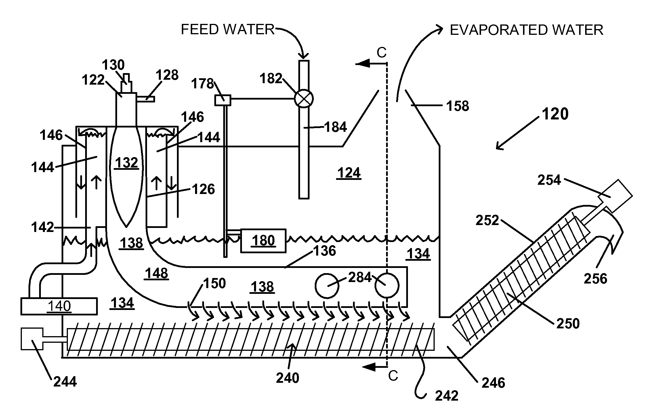
[0039]As used herein, unless otherwise specifically stated, the term “produced water” includes water produced from a hydrocarbon well, e.g., a gas or oil well, whether land-based or offshore, including water escaping or removed from the well at any stage of production, and further includes any other water from any other source, which water needs to be disposed of and cannot be simply poured on the ground, flowed into a waterway, or otherwise put “down the drain” into a sewage or septic system, for reasons such as toxicity, governmental regulations or for any other reason. This definition thus includes water from sources such as landfill runoff and leachate, water from waste disposal sites such as landfills and waste lagoons, water from areas such as airports or parking lots that, once collected, cannot be disposed of by other conventional, simple methods such as noted above. It is foreseeable that collection of runoff water from paved areas, such as parking lots, may eventually be r...


PUM

PropertyMeasurementUnit
temperatureaaaaaaaaaa
angleaaaaaaaaaa

Abstract

The present invention relates to a method of disposing of produced water and to a produced water disposal apparatus including a container for receiving and holding produced water; and a burner having a combustion chamber, wherein at least a portion of the combustion chamber is submerged in the water and the submerged portion of the combustion chamber comprises a sparger tube through which combustion gases emerge into, mix with and agitate the water. The present invention further relates to a mechanism for removing debris from the produced water disposal apparatus. In one embodiment, heat is supplied from an externally operated combustion system, rather than the submerged combustion. In one embodiment, the apparatus provides a concentrator, in which a solute can be removed and recovered from an aqueous medium containing the solute.

Description

CROSS-REFERENCE TO RELATED APPLICATIONS[0001]The present invention is related to and claims benefit under 35 U.S.C. §119 to previously filed, co-ending U.S. Provisional Application No. 60 / 865,450, filed Nov. 13, 2006, U.S. Provisional Application No. 60 / 866,354, filed Nov. 17, 2006, and U.S. Provisional Application No. 60 / 883,226, filed Jan. 3, 2007, the disclosure of each of which is hereby incorporated by reference.FIELD OF THE INVENTION[0002]This invention relates to an apparatus for disposing of water at the maximum rate and efficiency. More particularly, the present invention relates to a water disposal system including a sparger tube type submerged combustion apparatus, for disposing of water produced, for example, from a hydrocarbon well.BACKGROUND OF THE INVENTION[0003]Submerged combustion is a method of heating whereby hot products of combustion are forced through a medium to heat the medium. The heat exchange occurs directly between the hot products of combustion and the m...

Claims


Application Information

Patent Timeline
Patent Type & Authority Patents(United States)
IPC IPC(8): F22B37/48
CPCB01D1/0058B01D1/14C02F1/04B01D21/2461C02F1/048C02F1/10C02F1/16C02F2101/30C02F2101/32C02F2201/008C02F2209/40C02F2209/42
Inventor SMITH, DAVID G.
Owner TDU LLC
Why Eureka
Try Eureka