Magnetic resonance imaging apparatus
a magnetic resonance imaging and apparatus technology, applied in the field of magnetic resonance imaging apparatus, can solve the problems of gap generation, motion artifact generation over the entire, translation accuracy, etc., and achieve the effect of reducing the deterioration of image quality and low level of table movement accuracy
- Summary
- Abstract
- Description
- Claims
- Application Information
AI Technical Summary
Benefits of technology
Problems solved by technology
Method used
Image
Examples
embodiment 1
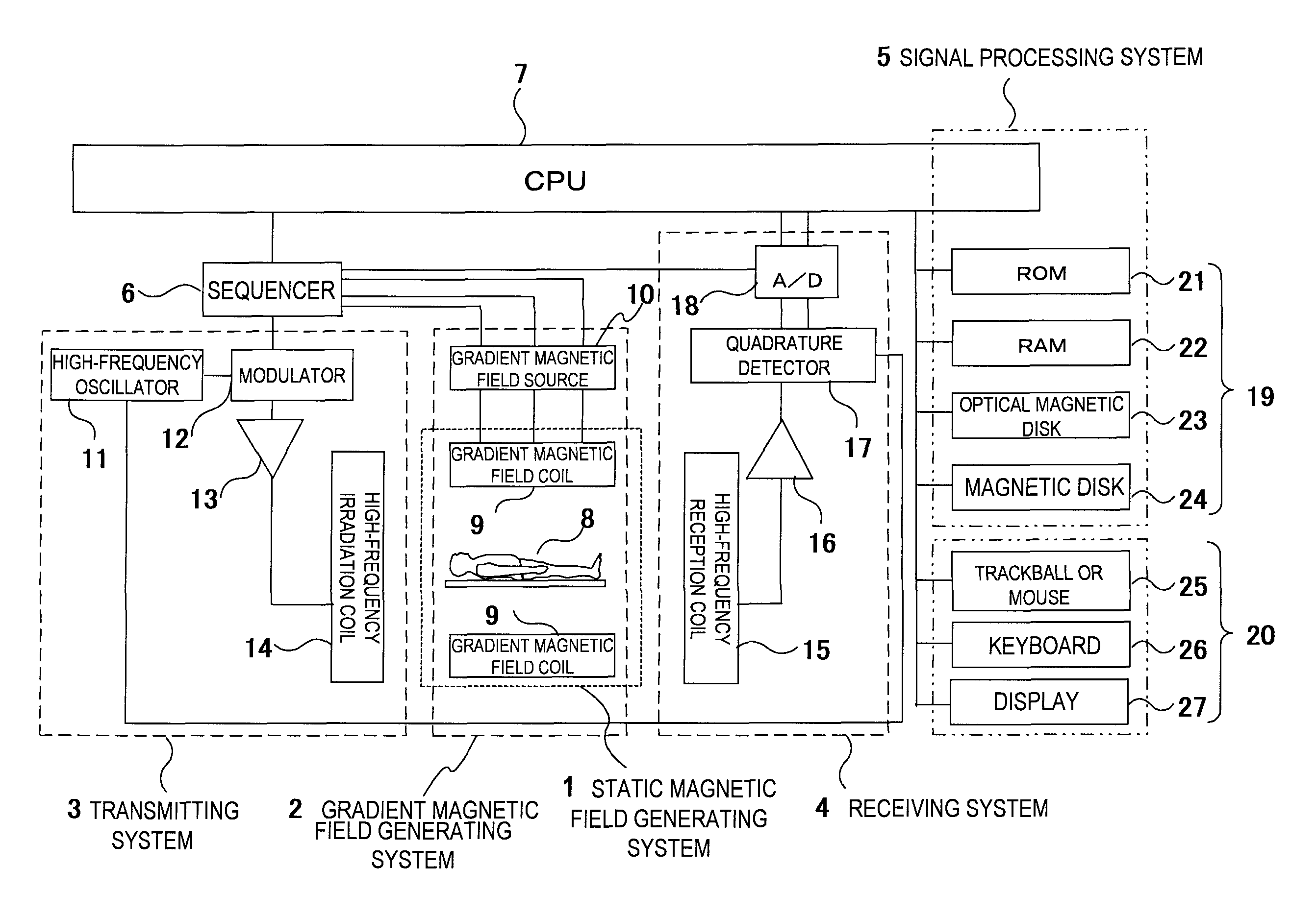
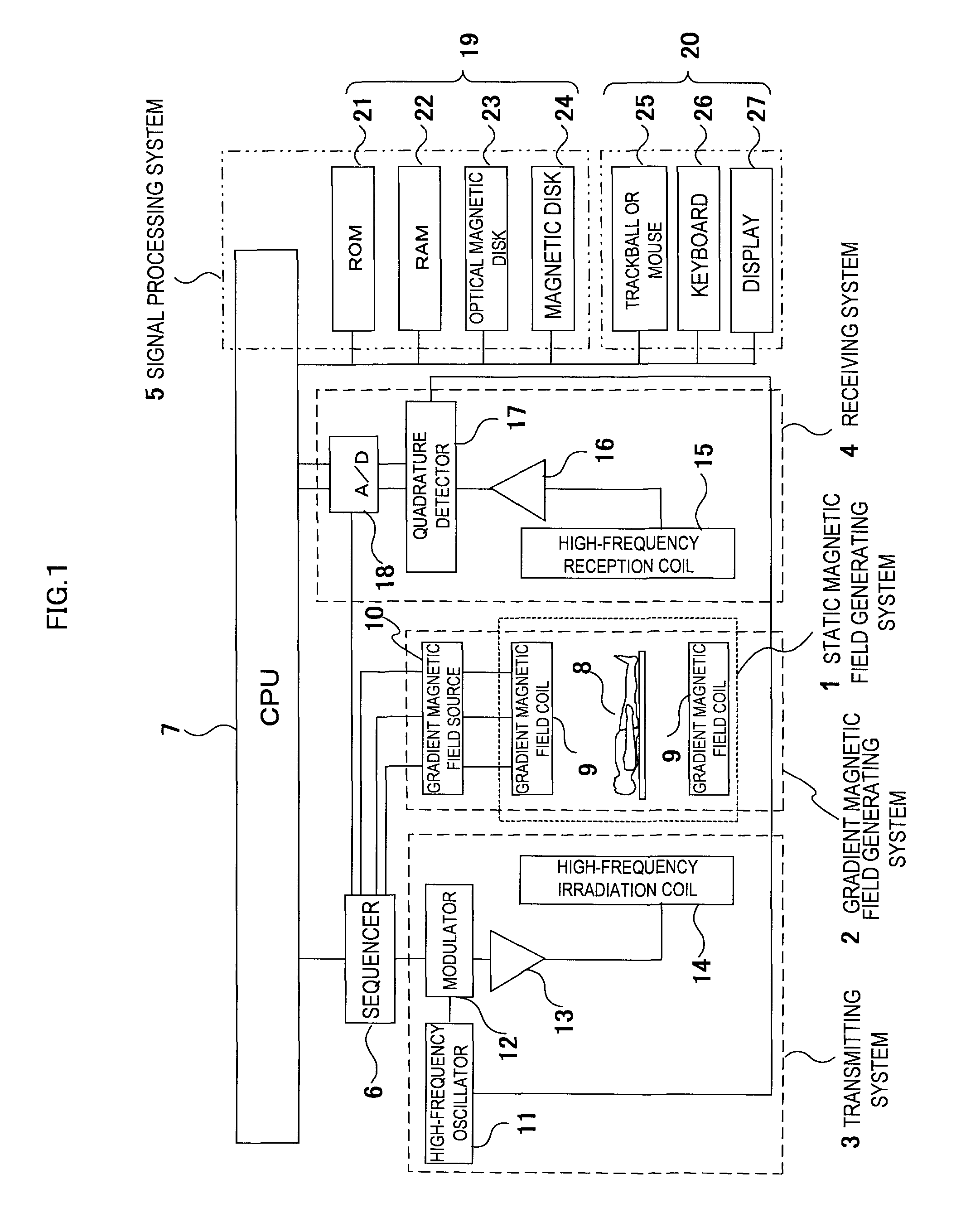
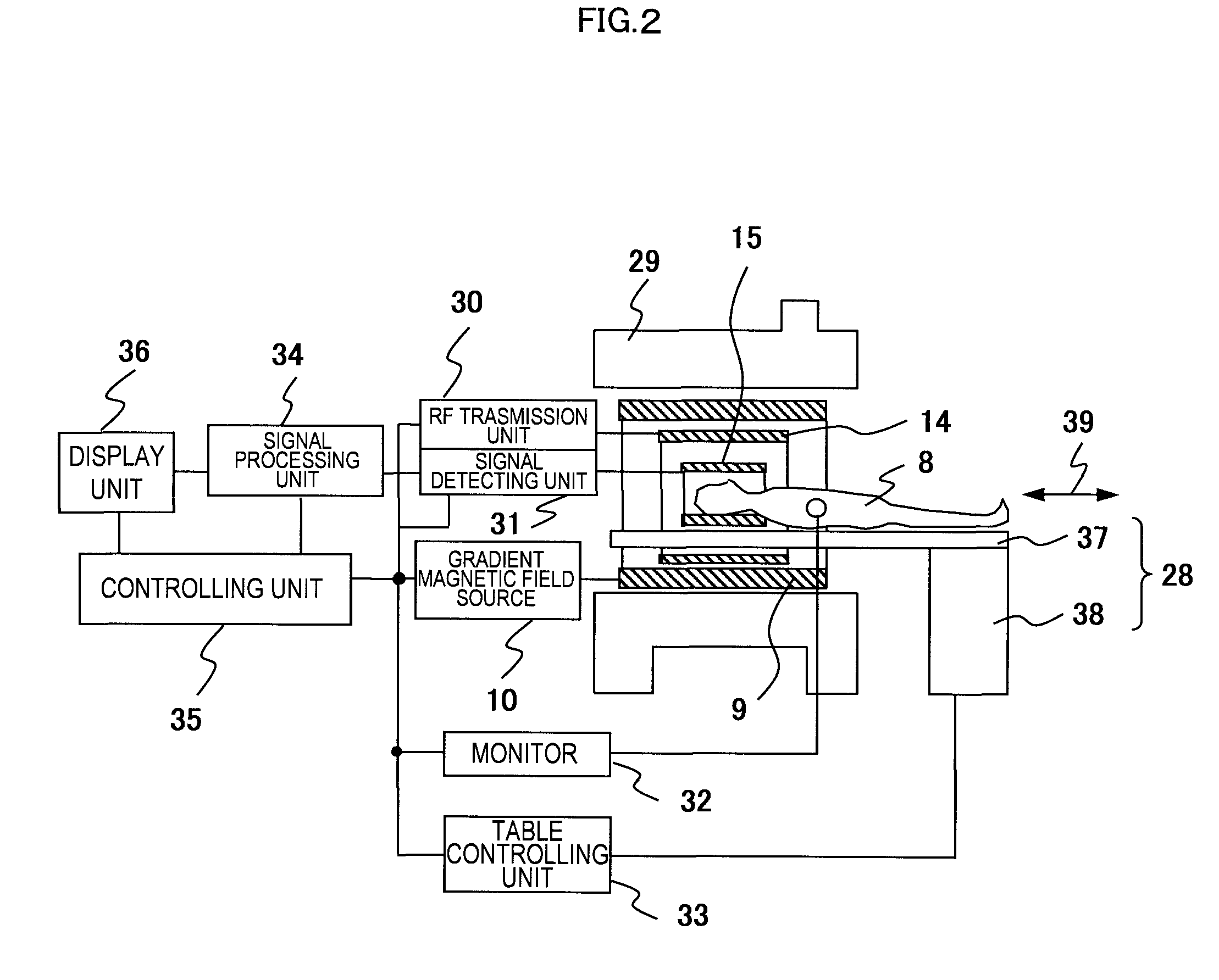
[0041]Next, the concrete configuration of the MRI apparatus in embodiment 1 will be described using FIG. 2. In FIG. 2, the MRI apparatus comprises a bed 28 on which the object 8 is placed, a magnet 29 for generating a static magnetic field around the object 8, a gradient magnetic field coil 9 for generating a gradient magnetic field in the imaging space of the static magnetic field space, a high-frequency (RF) irradiation coil 14 for generating a high-frequency magnetic, field in the imaging space, and a high-frequency reception coil (RF probe) 15 for detecting an NMR signal produced from the object 8. The MRI apparatus further comprises a gradient magnetic field source 10, an RF transmission unit 30, a signal detecting unit 31, a monitor 32, a bed control unit 33, a signal processing unit 34, a control unit 35 and a display unit 36.
[0042]The gradient magnetic field coil 9 comprises a gradient magnetic field coil in X, Y and Z-directions, and generates a gradient magnetic field in a...
embodiment 2
[0067]The MRI apparatus of embodiment 2 related to the present invention will be described using FIGS. 10 (a), (b) and (c). The MRI apparatus of the embodiment 2 is configured similar as the embodiment 1 in obtaining an image of the object while recognizing the position of the table 37 by the navigator echo, but different in not using the scale fixed on the table and in using the structure of the object 8 as an index for recognizing the position.
[0068]First, FIG. 10 (a) shows the schematic view of the apparatus configuration in the present embodiment viewing from the side of the object. In accordance with FIG. 10 (a), a navigator echo acquisition region 101 is set in the inside of the object 8, and a navigator echo is obtained by the same navigator sequence as the embodiment 1. FIG. 10 (b) shows the cross-sectional image 102, and the navigator echo acquisition region 101 is placed inside of the object 8. The echo signal is A / D converted into a time-series signal by the signal detect...
embodiment 3
[0072]The MRI apparatus of the embodiment 3 related to the present invention will be described using FIGS. 11 (a)˜(c) and FIG. 12. Embodiment 3 has the same configuration as the embodiment 1 in obtaining an image of an object while monitoring the position of the table 37 by the navigator echo, but is different in that it continuously monitors the table translation position using the phase contrast (PC) method in the navigator sequence.
[0073]First, FIG. 11 (a) shows a schematic view of the apparatus configuration in the present embodiment viewing from the side of an object being laid on the table. As shown in FIG. 11 (a), the scale 111 configured by a substance that generates NMR signals is mounted on the table 37. The scale in the embodiment 3, however, has a prismatic shape homogeneous in longitudinal direction, not the comb shape as in the embodiment 1. In this embodiment, the translation distance of the table 37 is measured by obtaining the echo signal with respect to the scale 1...
PUM
 Abstract
Description
Claims
Application Information
 - R&D
- Intellectual Property
- Life Sciences
- Materials
- Tech Scout
- Unparalleled Data Quality
- Higher Quality Content
- 60% Fewer Hallucinations
Browse by: Latest US Patents, China's latest patents, Technical Efficacy Thesaurus, Application Domain, Technology Topic, Popular Technical Reports.
© 2025 PatSnap. All rights reserved.Legal|Privacy policy|Modern Slavery Act Transparency Statement|Sitemap|About US| Contact US: help@patsnap.com


