Boosted write driver for transmission line with reduction in parasitic effect of protection devices

Inactive Publication Date: 2010-12-07
MARVELL INT LTD
View PDF11 Cites 9 Cited by
  • Summary
  • Abstract
  • Description
  • Claims
  • Application Information

AI Technical Summary

Benefits of technology

[0016]The present invention addresses the foregoing disadvantageous effect

Problems solved by technology

In practical devices, switches S1 through S4 are implemented in MOS or bipolar transistor fabrication, and such transistors cannot withstand the large voltage swings that occur in the transition between positive-going and negative-going current flow.
MOS or bipolar transistor devices cannot withstand s

Method used


Image

  • Boosted write driver for transmission line with reduction in parasitic effect of protection devices
  • Boosted write driver for transmission line with reduction in parasitic effect of protection devices
  • Boosted write driver for transmission line with reduction in parasitic effect of protection devices

Examples


first embodiment

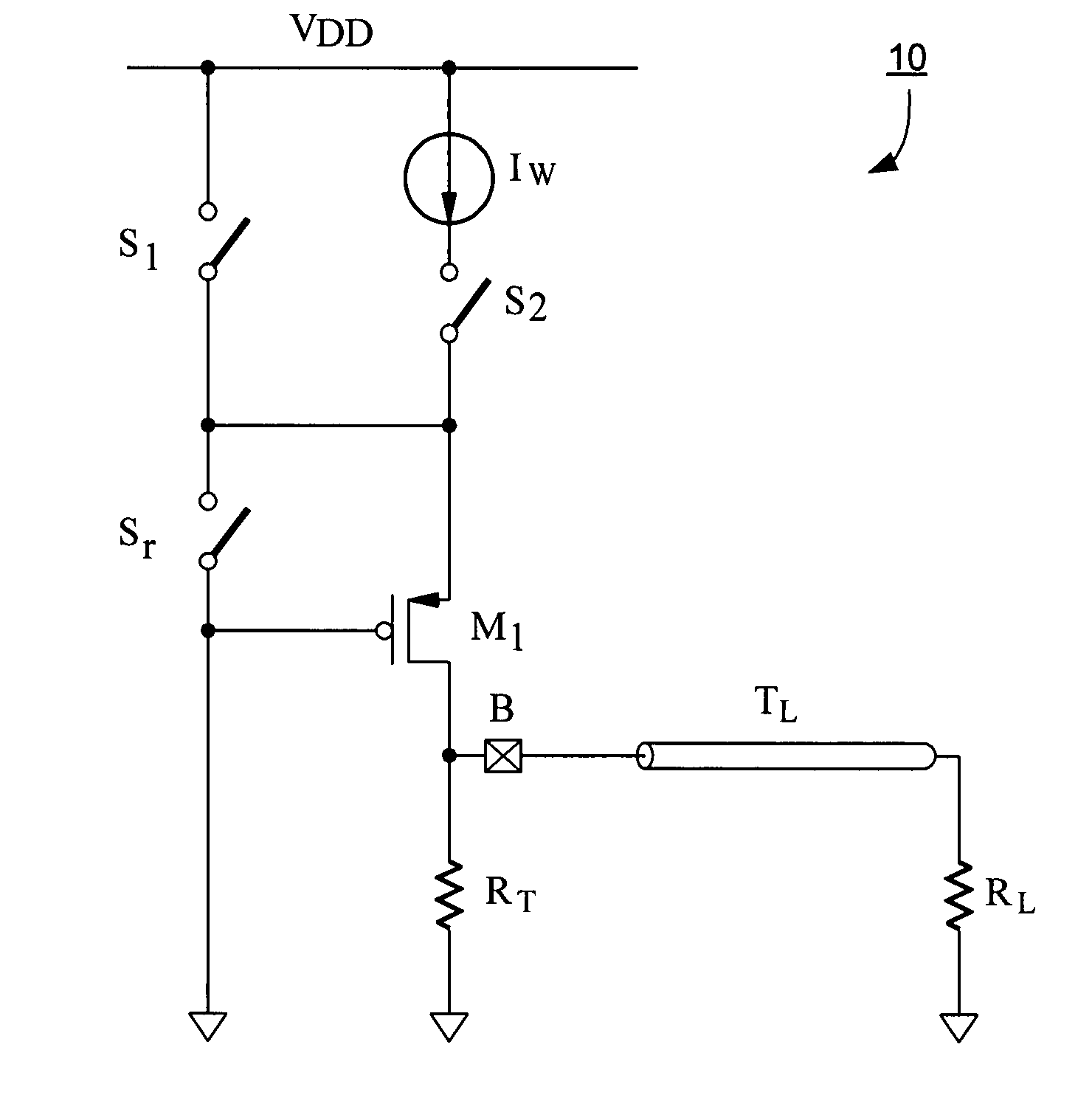
[0036]FIG. 5 is a view showing a circuit diagram according to the invention. For purposes of simplified explanation, the circuit diagram of FIG. 5 shows only the upper portion of driver circuitry 10. It will be appreciated that similar circuitry is provided for a lower portion of driver circuitry 10, constituting a section that leads to voltage VEE.

[0037]As shown in FIG. 5, drive circuitry 10 drives a load RL over a transmission line TL. Drive circuitry 10 includes a connector (B) for connection to the transmission line. In one example, the load is an inductive load such as a magnetic head of a hard disk drive, and the transmission line TL is twisted pair, coaxial cabling, flat bonded, flat ribbon, or other suitable transmission line.

[0038]The drive circuit includes a termination resistor RT whose impedance preferably matches the impedance Z0 of the transmission line.

[0039]Drive circuitry 10 includes a current source IW connected between VDD and VSS through signal switch S2 which is...

second embodiment

[0044]FIG. 7 shows the invention, in the form of a simplified circuit for driving a differential output along a pair of transmission lines that differentially drive a load RL. The transmission lines may or may not have the same characteristics, and indeed it is common for the transmission lines to have different lengths. Load RL is depicted as a resistive load, but in general it can be any load including an inductive load, such as a magnetic head for a hard disk drive.

[0045]The differential drive circuitry 20 shown in FIG. 7 includes a pair of mirror-image halves 21 and 22. With respect to half 21, current source IW is connected through a semiconductor signal switch SS1 and protection device M1 to a connector for one of the pair of transmission lines. A semiconductor boost switch SB1 is also connected through protection device M1 to the connector to the transmission line. Protection device M1 is a semiconductor protection device, preferably a large p-type device, which protects both...


PUM


Abstract

A driver for driving a load over a transmission line, such as driving the magnetic head of a hard disk drive. The driver includes a signal switch for switching the signal to the load during a signal period, and a boost switch for boosting the signal during a boost period, so as to decrease rise time of the signal at the load by deliberately injecting an overshoot. A switchable protection device protects the signal switch and the boost switch. The protection device includes a reflection-suppression switch which is pulsed during a time corresponding to the expected return of a reflection corresponding to the overshoot signal, so as to force the protection device into saturation mode. Since the protection device is in the saturation mode during the return reflection of the boost signal, the returned reflection sees a matched impedance and thus reduces a re-reflection back to the load.

Description

CROSS-REFERENCE TO RELATED APPLICATION[0001]This application claims the benefit of U.S. Provisional Patent Application No. 60 / 826,260, filed Sep. 20, 2006, the contents of which are hereby incorporated by reference as if fully stated herein.FIELD OF THE INVENTION[0002]The present invention relates to a driver for a transmission line in which the driver includes protection devices for the switches therein, and particularly relates to a driver in which the parasitic effects of such protection devices are reduced.BACKGROUND OF THE INVENTION[0003]In the continuing effort to increase the storage capacity of hard disk drives, one area of development has focused on decreasing the rise time (or, equivalently, increasing the “slew rate”) of the write current applied to the magnetic head. Generally speaking, if the rise time can be decreased, then it is possible to record more data bits per second on the hard disk drive, resulting in increased storage capacity.[0004]One way in which rise time...

Claims


Application Information

Patent Timeline
IPC IPC(8): G11B5/09
CPCG11B5/02G11B5/022G11B2005/001
Inventor TAN, KIEN BENGMIAO, XIAO YU
Owner MARVELL INT LTD
Why Eureka
Try Eureka