Switching amplifier driven by a controlled power supply

Inactive Publication Date: 2010-12-14
MUSIC GROUP IP
View PDF3 Cites 83 Cited by
  • Summary
  • Abstract
  • Description
  • Claims
  • Application Information

AI Technical Summary

Benefits of technology

[0074]According to the present invention an advantageous method of driving switching amplifiers by use of tracking power supplies is provided. The method enables many benefits of switching amplifiers to be obtained together with the benefits of utilizing a tracking power supply. Among many things, this reduces power consumption, reduces EMI noise and enables using

Problems solved by technology

Some of the disadvantages, however, that still exist with the known switching amplifiers are related to the way power is supplied to the amplifier.
The continuous high DC voltage even at idle times causes unnecessary much noise and EMI problems as the noise is proportional with the supply voltage, and the power consumption becomes unnecessarily high as most of the loss is proportional to the square of the supply voltage.
Whereas it is relatively simple to establish a DC supply volta

Method used


Image

  • Switching amplifier driven by a controlled power supply
  • Switching amplifier driven by a controlled power supply
  • Switching amplifier driven by a controlled power supply

Examples


Embodiment Construction

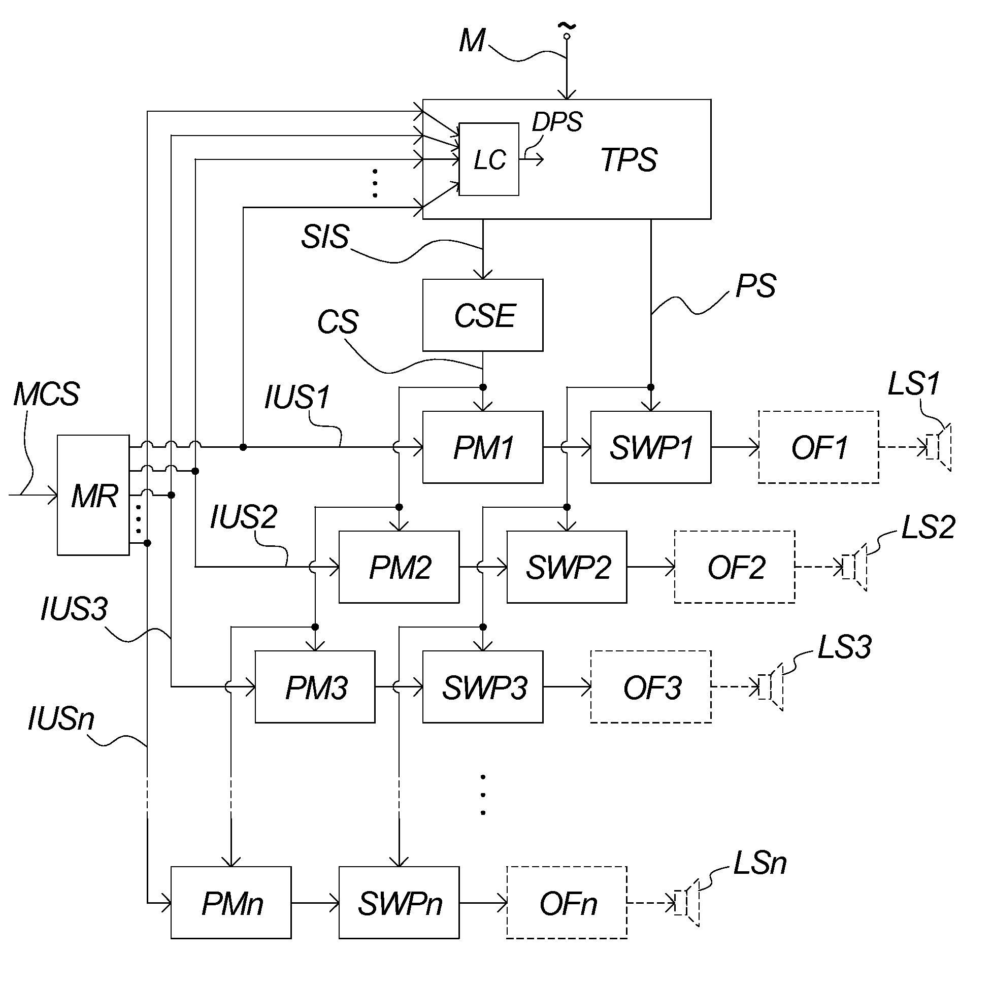
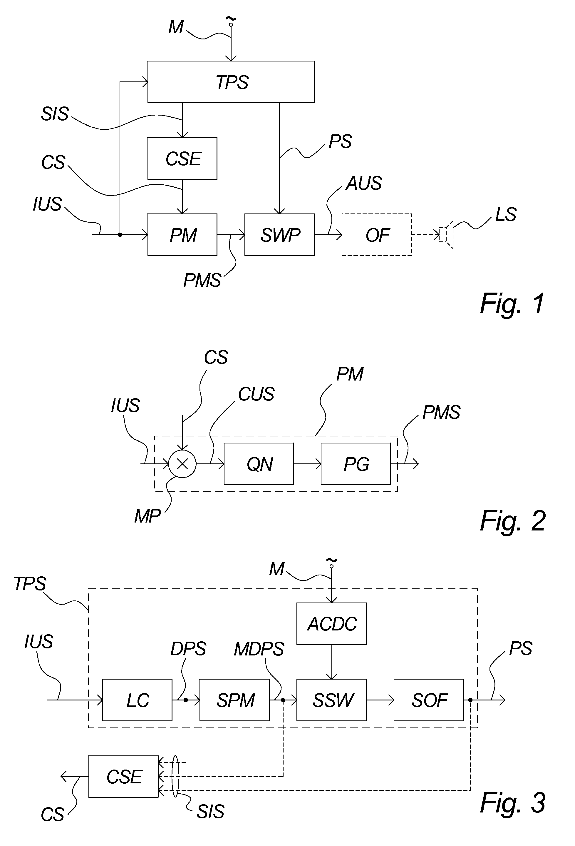
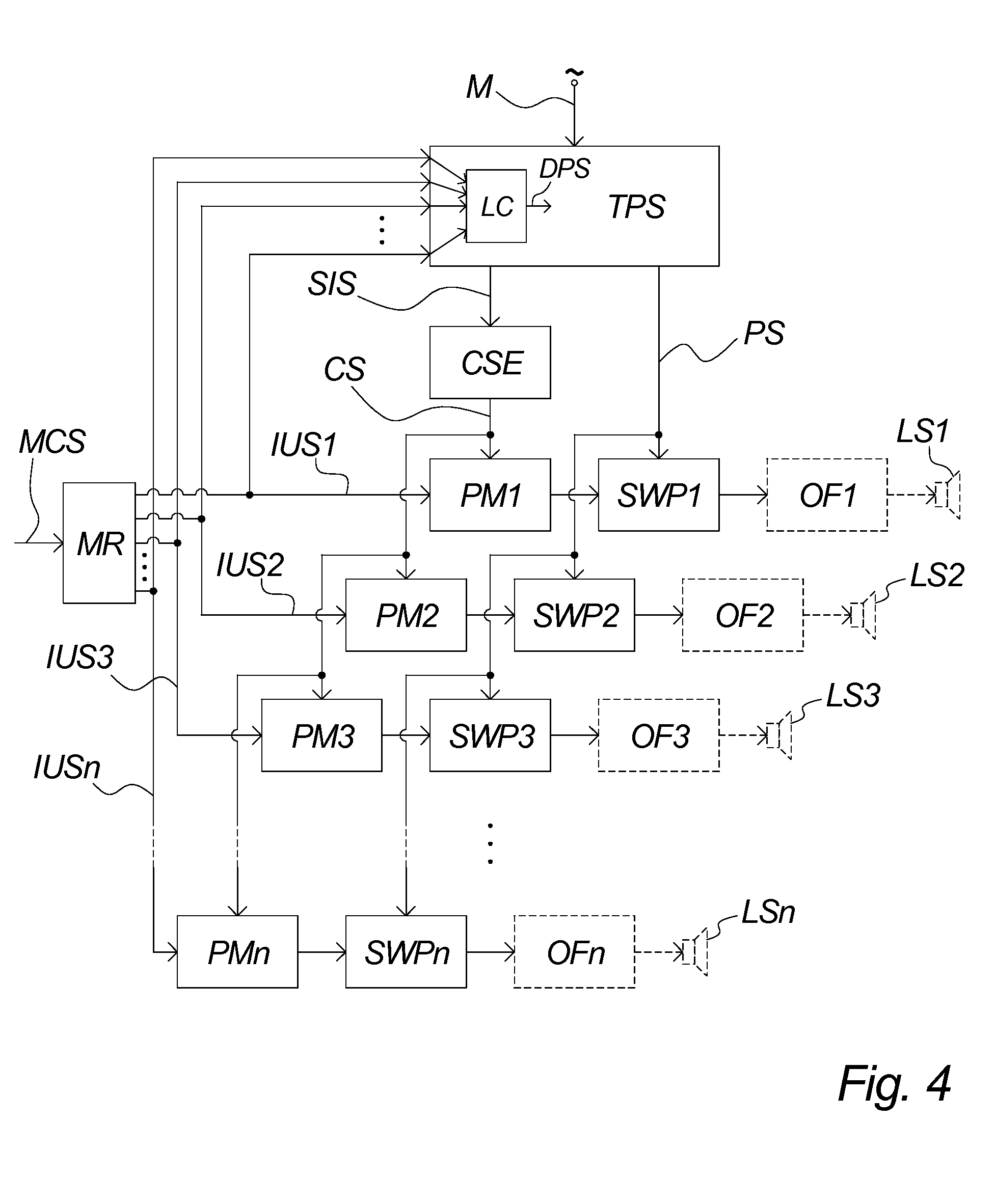
[0103]FIG. 1 illustrates an embodiment of a switching amplifier according to the present invention. An input utility signal IUS is turned into a pulse modulated signal PMS by a pulse modulator PM. A switching power stage SWP establishes an amplified utility signal AUS on the basis of the pulse modulated signal PMS. In a typical embodiment, an output filter OF further demodulates the pulsed amplified utility signal AUS for reproduction by e.g. a loudspeaker LS. In a preferred embodiment the input utility signal is an audio signal, and the amplifier optimised for audio.

[0104]The pulse modulator PM and switching power stage SWP may as long as they together carry out a kind of multiplication between the power supply voltage and input utility signal comprise any class-D or switching amplifier technology, based on any type of pulse modulation, e.g. 2-level PWM, 3-level PWM, multilevel PWM, PDM, etc., any type of switching power stage, e.g. full-bridge, half-bridge, single-ended, different...


PUM


Abstract

The invention relates to a switching amplifier comprising at least one pulse modulator arranged for modulating at least one input utility signal into at least one pulse modulated signal and at least one switching power stage arranged to establish at least one amplified utility signal on the basis of said at least one pulse modulated signal and a power signal, said power signal being delivered by a tracking power supply at least partly controlled by said at least one input utility signal, characterized in that said switching amplifier is arranged to process said at least one input utility signal according to a correction signal established by a correction signal estimator on the basis of a supply information signal derived from said tracking power supply.
According to the present invention an advantageous switching amplifier enabling use of a tracking power supply is provided. Thereby the many benefits of switching amplifiers can now be obtained together with the benefits of utilizing a tracking power supply. Among many things, this reduces power consumption, reduces EMI noise and enables using more of the dynamic range available for the utility signal during the pulse modulation. The last advantage further renders noise introduced by the power supply and the switching output stage less significant, as the signal-to-noise ratio in the power stage is greatly improved due to the utilization of the full dynamic range enabled by using a tracking power supply.

Description

CROSS-REFERENCE TO RELATED APPLICATION[0001]This application is related to and claims the benefit of U.S. Provisional Patent Application Ser. No. 61 / 015,459 filed on 20 Dec. 2007. The contents of said provisional application are herein incorporated by reference in their entirety.FIELD OF THE INVENTION[0002]The present invention relates to switching amplifiers, in particular how to supply an open-loop switching amplifier from a tracking or variable power supply.BACKGROUND OF THE INVENTION[0003]Switching amplifiers, class-D amplifiers, PWM amplifiers, etc., are amplifiers that work by in principle multiplying the input utility signal, e.g. an audio signal, with a power signal, e.g. a DC voltage. They have many advantages and are becoming more and more popular in both consumer and professional markets as their quality increase.[0004]Some of the disadvantages, however, that still exist with the known switching amplifiers are related to the way power is supplied to the amplifier. In orde...

Claims


Application Information

Patent Timeline
IPC IPC(8): H03F3/38
CPCH03F3/217H03F3/68H03F1/0227H03F2200/114
Inventor ARKNAES-PEDERSEN, LARS
Owner MUSIC GROUP IP
Why Eureka
Try Eureka