Electro active compression bandage
a compression bandage and active technology, applied in the direction of massage belts, ligaments, therapy, etc., can solve the problems of bandage being associated with numerous problems, unable to fully understand the underlying pressure, and unable to achieve the effect of improving the pressure profil
- Summary
- Abstract
- Description
- Claims
- Application Information
AI Technical Summary
Benefits of technology
Problems solved by technology
Method used
Image
Examples
first embodiment
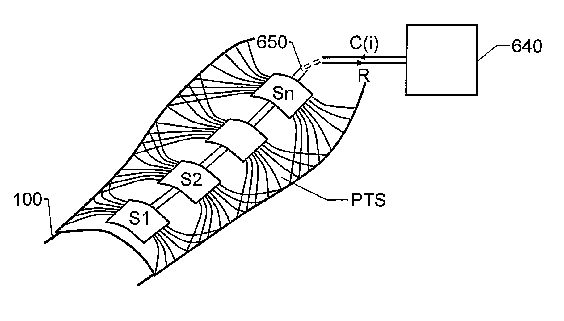
[0070]FIG. 2 shows a perspective view of a device according to the invention. Here, two segments S1 and S2 are shown. However, according to the invention, the device may include any number of segments larger than two. The pressure transition system PTS is at least positioned between the first and second segments S1 and S2. Thereby, the pressure transition system PTS may bridge over pressure profiles and tension forces from one segment to another, i.e. from S1 to S2, from S2 to S1, etc. Here, different degrees of coupling between the segments may be attained depending upon which fiber directions that are chosen for a fabric used in the pressure transition system PTS.
[0071]As mentioned above, according to the invention, each segment S1 and S2 includes an actuator A1 and A2 respectively. Here, the segments S1 and S2 include a respective strap member 240 and 250, and the actuators A1 and A2 are located at one end of each segment. The actuators A1 and A2 are further attached to the strap...
second embodiment
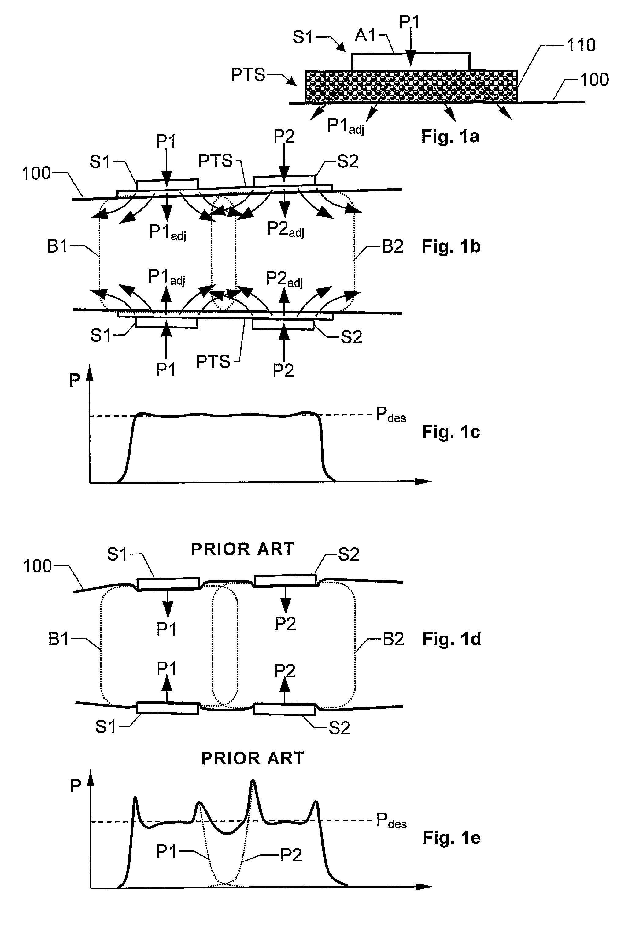
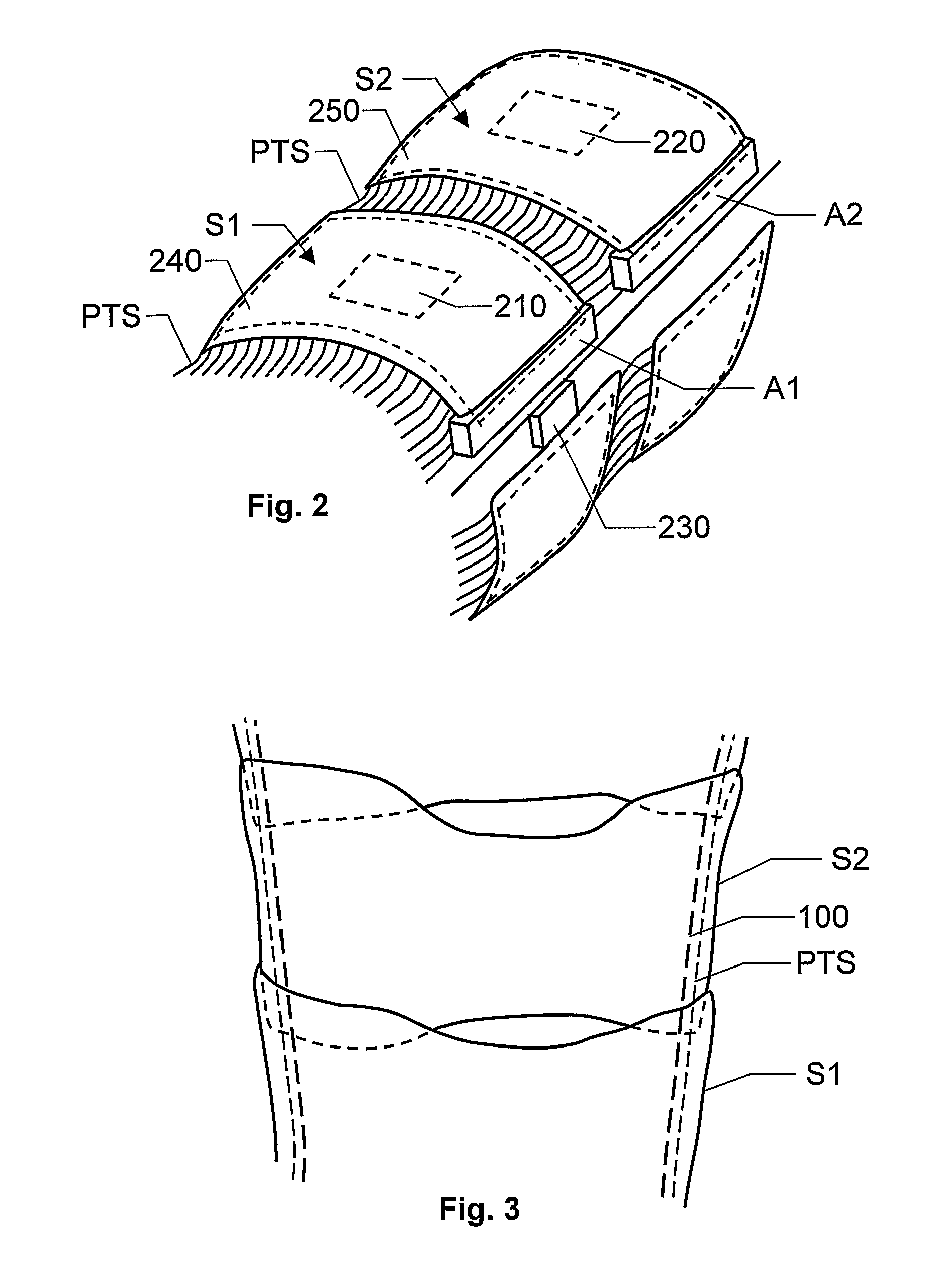
[0077]FIG. 3 shows a perspective view of a device according to the invention. Here, each of a number of segments S1, S2, etc. at least partially encloses a body part 100. Moreover, the segments are arranged such that a portion of one segment S1 covers a portion of a neighboring segment S2, and so on. Thereby, analogous to the embodiment described above with reference to FIG. 1b, relatively smoothed-out, or fuzzy, pressure profiles may be applied to the body part 100 in response to control signals in respect of the segments S1 and S2. Moreover, to redistribute these pressure profiles a pressure transition system PTS is located between the segments and the body part 100. Preferably, the pressure transition system PTS has a low-friction surface towards the segments S1 and S2, so that smooth tangential movements of the segments S1 and S2 are allowed relative to the pressure transition system PTS.
[0078]FIGS. 4a-b show two cross-section views of one embodiment of the proposed pressure tra...
PUM
| Property | Measurement | Unit |
|---|---|---|
| pressure | aaaaa | aaaaa |
| pressure | aaaaa | aaaaa |
| pressure | aaaaa | aaaaa |
Abstract
Description
Claims
Application Information
 - R&D
- Intellectual Property
- Life Sciences
- Materials
- Tech Scout
- Unparalleled Data Quality
- Higher Quality Content
- 60% Fewer Hallucinations
Browse by: Latest US Patents, China's latest patents, Technical Efficacy Thesaurus, Application Domain, Technology Topic, Popular Technical Reports.
© 2025 PatSnap. All rights reserved.Legal|Privacy policy|Modern Slavery Act Transparency Statement|Sitemap|About US| Contact US: help@patsnap.com


