
Micro-reactor and method of manufacturing the same

a micro-reactor and manufacturing method technology, applied in the field of micro-reactors, can solve the problems of poor heat utilization efficiency, impede the implementation of micro-reactors, and use of materials, so as to prevent contamination and deactivation of catalysts, suppress the amount of catalyst applied, and uniform catalyst applied

Inactive Publication Date: 2010-12-28
DAI NIPPON PRINTING CO LTD +2
View PDF14 Cites 8 Cited by
  • Summary
  • Abstract
  • Description
  • Claims
  • Application Information

AI Technical Summary

Benefits of technology

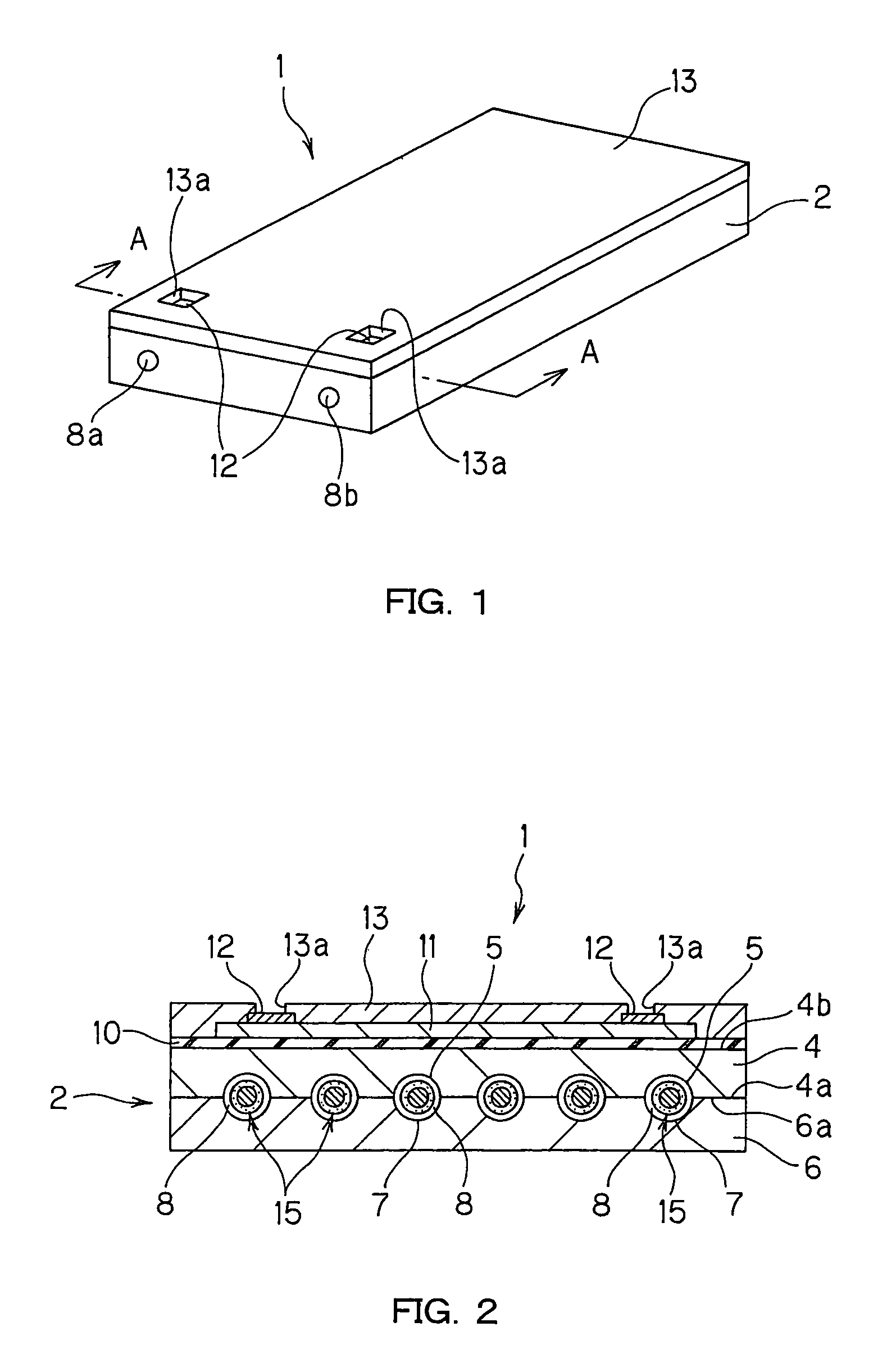
The present invention provides a microreactor that is small and efficient in catalytic reactions. The microreactor comprises a joined body with a flow path formed by a microchannel portion on at least one of the substrates, and a catalyst carrying member disposed in the flow path. The catalyst carrying member is produced independently of the formation of the microchannel portion on the substrate, which reduces variation in catalyst applying amount and prevents contamination and deactivation of the catalyst. The microreactor can be easily produced and has high reliability. The technical effects of the present invention are improved efficiency and reliability of the microreactor.

Problems solved by technology

However, since the conventional microreactor, including the microreactor for hydrogen production, carries the catalyst in the microchannel, it is necessary to select a material of the microreactor taking into account catalyst supportability thereof and therefore there have been those instances where there is no alternative but to use a material that is poor in heat utilization efficiency.
Further, there has been a problem that, in the process of applying a catalyst into a microchannel, cleanness of a substrate surface where the microchannel is formed is lost to thereby impede the microreactor production which is implemented by joining substrates together.
Further, there have been those instances where a catalyst supported in a microchannel is extremely contaminated or deactivated in a later process and therefore there has also been a problem that usable catalysts are limited and the production process management is difficult.
Moreover, the conventional microreactor has a low reaction efficiency and therefore a microreactor with a higher reaction efficiency has been demanded.

Method used


Image

  • Micro-reactor and method of manufacturing the same
  • Micro-reactor and method of manufacturing the same
  • Micro-reactor and method of manufacturing the same

Examples


fourth embodiment

[0083]FIG. 12 is a perspective view showing another embodiment of a microreactor of the present invention, and FIG. 13 is an enlarged longitudinal sectional view of the microreactor shown in FIG. 12, taken along line C-C. In FIGS. 12 and 13, the microreactor 61 of the present invention has a joined body 62 comprising a substrate 64 formed with a microchannel portion 65 on one surface 64a thereof, and a substrate (cover member) 66 joined to the surface 64a of the substrate 64 so as to cover the microchannel portion 65. Inside the joined body 62, there is formed a flow path 68 composed of the microchannel portion 65 and the substrate 66, and a catalyst carrying member 75 is disposed inside the flow path 68. The substrate (cover member) 66 is provided with a feed material inlet 66a and a product recovery port 66b which are located at both end portions of the flow path 68. Further, a heater 71 is provided on the surface 64b of the substrate 64 via an insulating layer 70. The heater 71 i...

first embodiment

[0089]FIGS. 14A to 14C and FIGS. 15A to 15C are process diagrams for describing one embodiment of the microreactor producing method of the present invention.

[0090]In FIGS. 14A to 14C and FIGS. 15A to 15C, description will be made using the foregoing microreactor 1 as an example.

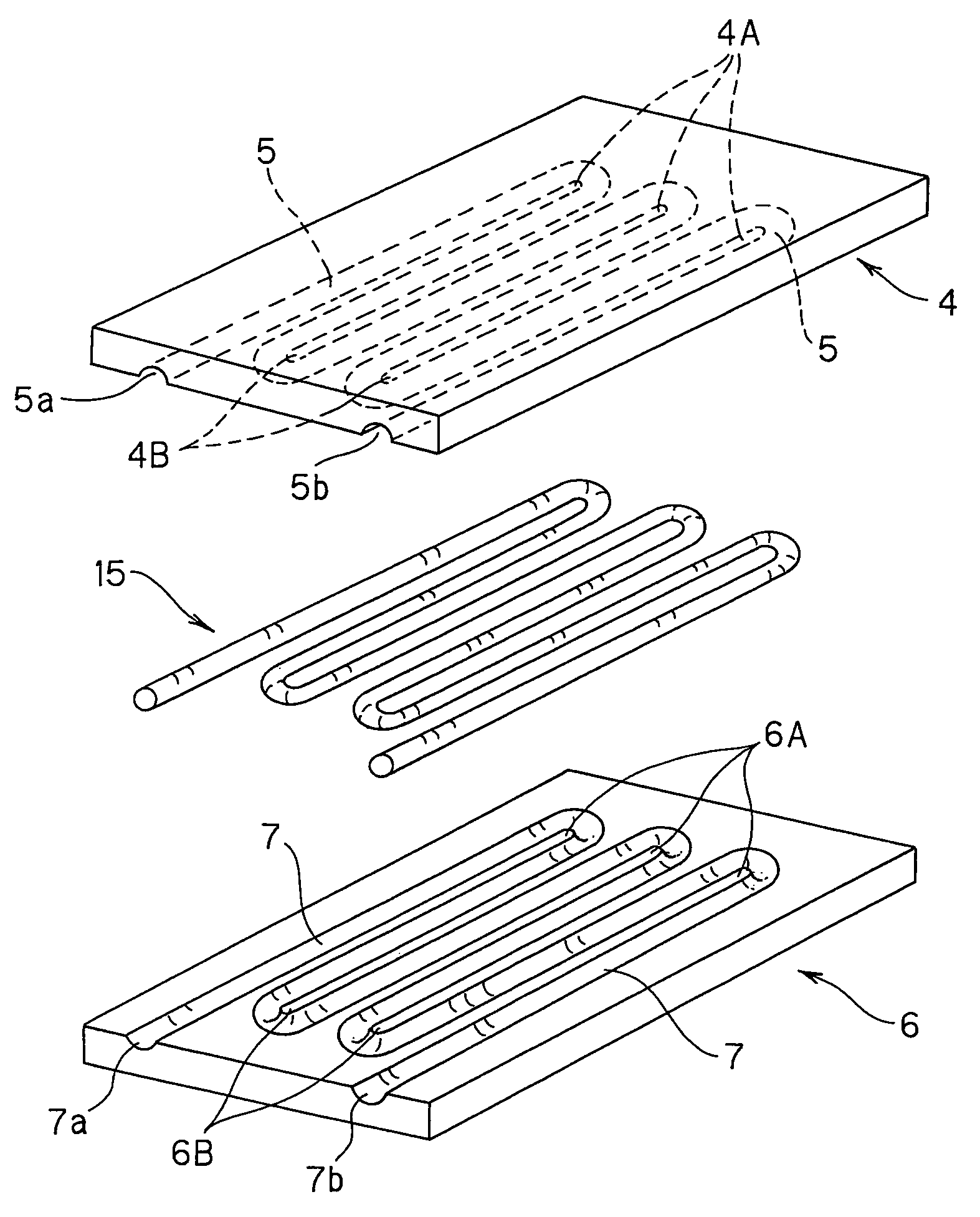
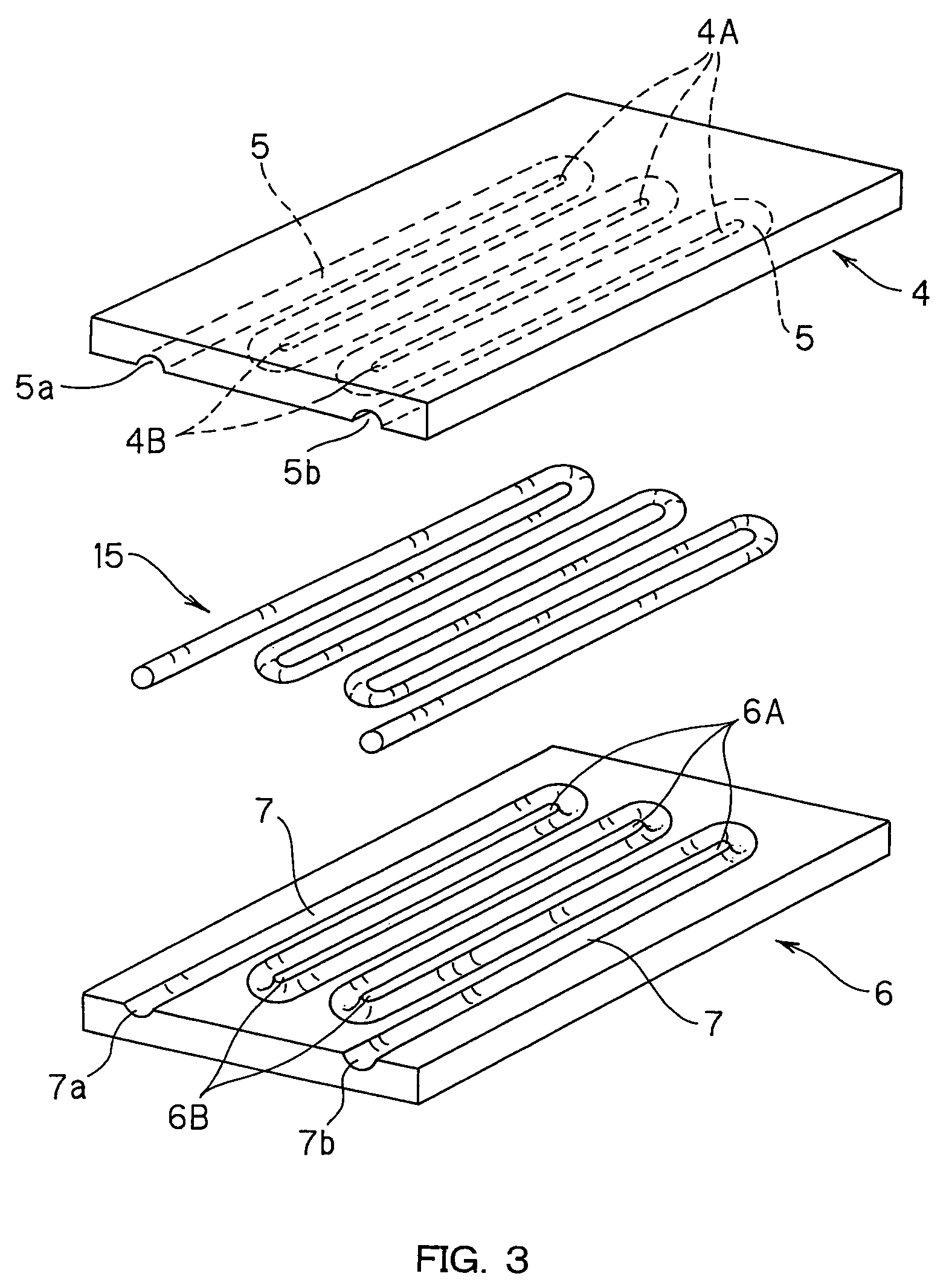
[0091]In the production method of the present invention, at the outset, in a channel portion forming process, a microchannel portion 5 is formed on one surface 4a of a substrate 4, and a microchannel portion 7 is formed on one surface 6a of a substrate 6 (FIG. 14A). The microchannel portion 5, 7 can be formed by forming a resist having a predetermined opening pattern on the surface 4a, 6a of the substrate 4, 6 and etching the substrate 4, 6 to leave comb-shaped ribs 4A and 4B, 6A and 6B by wet etching using the resist as a mask. It is also possible to form the microchannel portion 5, 7 by the use of router processing, press working, sandblasting method, or the like.

[0092]The metal substrates 4 and 6 form a pa...

second embodiment

[0107]FIGS. 16A to 16D and FIGS. 17A to 17B are process diagrams for describing another embodiment of the microreactor producing method of the present invention.

[0108]In FIGS. 16A to 16D and FIGS. 17A to 17B, description will be made using the foregoing microreactor 41 as an example.

[0109]In the production method of the present invention, at the outset, in a channel portion forming process, a microchannel portion 45 is formed on one surface 44a of a substrate 44, and a microchannel portion 47 is formed on one surface 46a of a substrate 46. Further, two through holes 44c and 44c are formed at predetermined portions of the microchannel portion 45 (FIG. 16A). The formation of the microchannel portions 45 and 47 on the substrates 44 and 46 can be implemented like the formation of the microchannel portions 5 and 7 on the substrates 4 and 6 in the foregoing embodiment. On the other hand, the formation of the through holes 44c and 44c can be implemented by forming a resist having predeterm...


PUM

PropertyMeasurementUnit
widthaaaaaaaaaa
widthaaaaaaaaaa
lengthaaaaaaaaaa

Abstract

A structure of a microreactor includes a joined body having a pair of substrates joined together, a flow path formed by a microchannel portion formed on a joining surface of at least one of the substrates, and a catalyst carrying member disposed in the flow path. In the production of such a microreactor, the catalyst carrying member is produced separately from formation of the joined body and the catalyst carrying member is disposed in the flow path at the time of forming the joined body.

Description

TECHNICAL FIELD[0001]The present invention relates to a microreactor and particularly a microreactor for allowing desired reactions to proceed by the use of a supported catalyst, and a production method of such a microreactor.BACKGROUND ART[0002]Hitherto, reactors employing catalysts have been used in various fields and optimally designed depending on the purpose.[0003]On the other hand, in recent years, attention has been paid to using hydrogen as fuel because of no generation of global warming gas such as carbon dioxide in terms of the global environmental protection, and of the high energy efficiency. Particularly, attention has been paid to fuel cells because they can directly convert hydrogen to electric power and enable the high energy conversion efficiency in the cogeneration system utilizing generated heat. The fuel cells have been hitherto employed under the particular conditions such as in the space development and the ocean development. Recently, however, the development ...

Claims


Application Information

Patent Timeline
Patent Type & Authority Patents(United States)
IPC IPC(8): H01M8/06B21D51/16B01J19/00B01J35/02B01J23/80B01J37/02C01B3/32C01B3/38
CPCB01J19/0093B01J37/0226C01B3/323C25D11/02C25D13/02C25D13/12B01J23/80Y10T29/49345B01J2219/00783B01J2219/00822B01J2219/00835B01J2219/0086B01J2219/00873C01B2203/0227C01B2203/1076Y10T156/10Y02P20/52
Inventor KIHARA, TAKESHIYAGI, HIROSHISUZUKI, KOICHIOGIWARA, YOSHIAKININOMIYA, JUNJIISHIKAWA, KAZUNORI
Owner DAI NIPPON PRINTING CO LTD
Learn More