
Electrode for fuel cell, membrane electrode composite and fuel cell, and method for manufacturing them

a fuel cell and membrane electrode technology, applied in the field of fuel cell electrodes, membrane electrode composites and fuel cells, can solve the problems of unsuitable stable supply of electric power, difficult to provide stable output, proton-conductive solid electrolyte, etc., and achieve the effect of maintaining power generation performance over a long period of time and stable outpu

Inactive Publication Date: 2011-01-18
KK TOSHIBA
View PDF10 Cites 9 Cited by
  • Summary
  • Abstract
  • Description
  • Claims
  • Application Information

AI Technical Summary

Benefits of technology

This configuration enables stable power generation over a wide temperature range from room temperature to 150°C, maintaining high proton and electron conductivity, thus ensuring long-term reliability and efficient fuel cell performance.

Problems solved by technology

Accordingly, it is difficult to provide stable output.
Accordingly, the proton-conductive solid electrolyte is unstable as a proton-conductive solid electrolyte in a fuel cell which produces water in the course of power generation, particularly a fuel cell using a liquid fuel, and thus is possibly unsuitable for stable supply of electric power for a long period of time.
Further, since there is a possibility that the sulfonic acid group is eliminated, the sulfonic acid group-containing borosiloxane electrolyte is considered as a material unsuitable for stable supply of electric power for a long period of time.
In the operation under high temperatures, however, the OH groups are eliminated upon drying resulting in lowered proton conductivity.
Further, since there is a possibility that the P2O5 component for glass skeleton formation is dissolved in water, it is difficult to stably supply electric power for a long period of time.
Since, however, the catalyst carrier does not have any proton conductivity, it is considered that the utilization efficiency of the catalyst and the formation of the three-phase interfaces are unsatisfactory.
Consequently, there is a possibility that the three-phase interface which causes an electrode reaction cannot be satisfactorily formed.

Method used


Image

  • Electrode for fuel cell, membrane electrode composite and fuel cell, and method for manufacturing them
  • Electrode for fuel cell, membrane electrode composite and fuel cell, and method for manufacturing them
  • Electrode for fuel cell, membrane electrode composite and fuel cell, and method for manufacturing them

Examples


first embodiment

[0038]At the outset, an electrode for a fuel cell in a first embodiment of the present invention will be described.

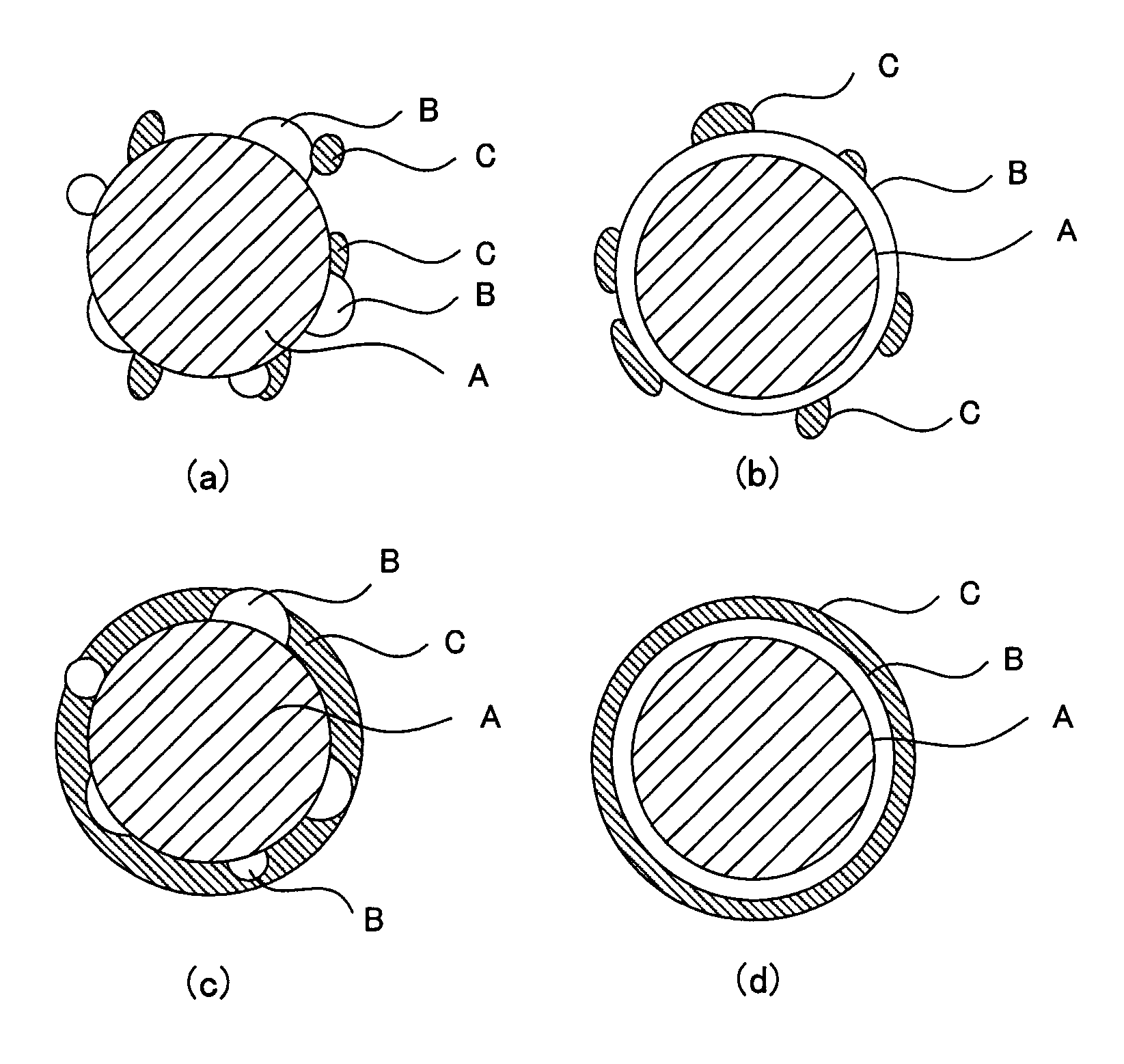
[0039]The electrode for a fuel cell in this embodiment comprises a catalyst layer comprising a proton-conductive inorganic oxide with an oxidation-reduction catalyst supported thereon and an organic polymer binder. The catalyst layer mainly functions as a reaction field for an oxidation-reduction reaction of a fuel and an oxidizing agent in the electrode for a fuel cell. The catalyst layer also functions as a transfer layer for protons and electrons which are produced and consumed by the oxidation-reduction reaction.

[0040]The catalyst layer in this embodiment comprises a proton conductor having electron conductivity and an inorganic oxide. This inorganic oxide comprises[0041]a catalyst carrier comprising at least one material selected from the group consisting of tin(Sn)-doped In2O3, fluorine(F)-doped SnO2, and antimony(Sb)-doped SnO2,[0042]an oxide particle phase provi...

second embodiment

[0070]The second embodiment of the present invention relates to a membrane electrode composite comprising a fuel electrode, an oxidizer electrode, and an electrolyte membrane disposed between the fuel electrode and the oxidizer electrode. At least one of the fuel electrode and the oxidizer electrode comprises a catalyst layer, and the construction and effect of the catalyst layer is the same as those described above in connection with the first embodiment.

[0071]The electrolyte membrane is not particularly limited, and examples thereof include perfluorosulfonic acid-containing polymer electrolyte membranes, for example, Nafion (tradename, manufactured by Du Pont). Since, however, stable output can be provided even under elevated temperatures, a proton-conductive solid electrolyte membrane comprising an oxide superacid contained in an organic polymer may be selected.

[0072]The oxide superacid contained in the organic polymer comprises an oxide carrier H containing at least one element ...

third embodiment

[0098]The fuel cell in the third embodiment comprises the membrane electrode composite in the second embodiment.

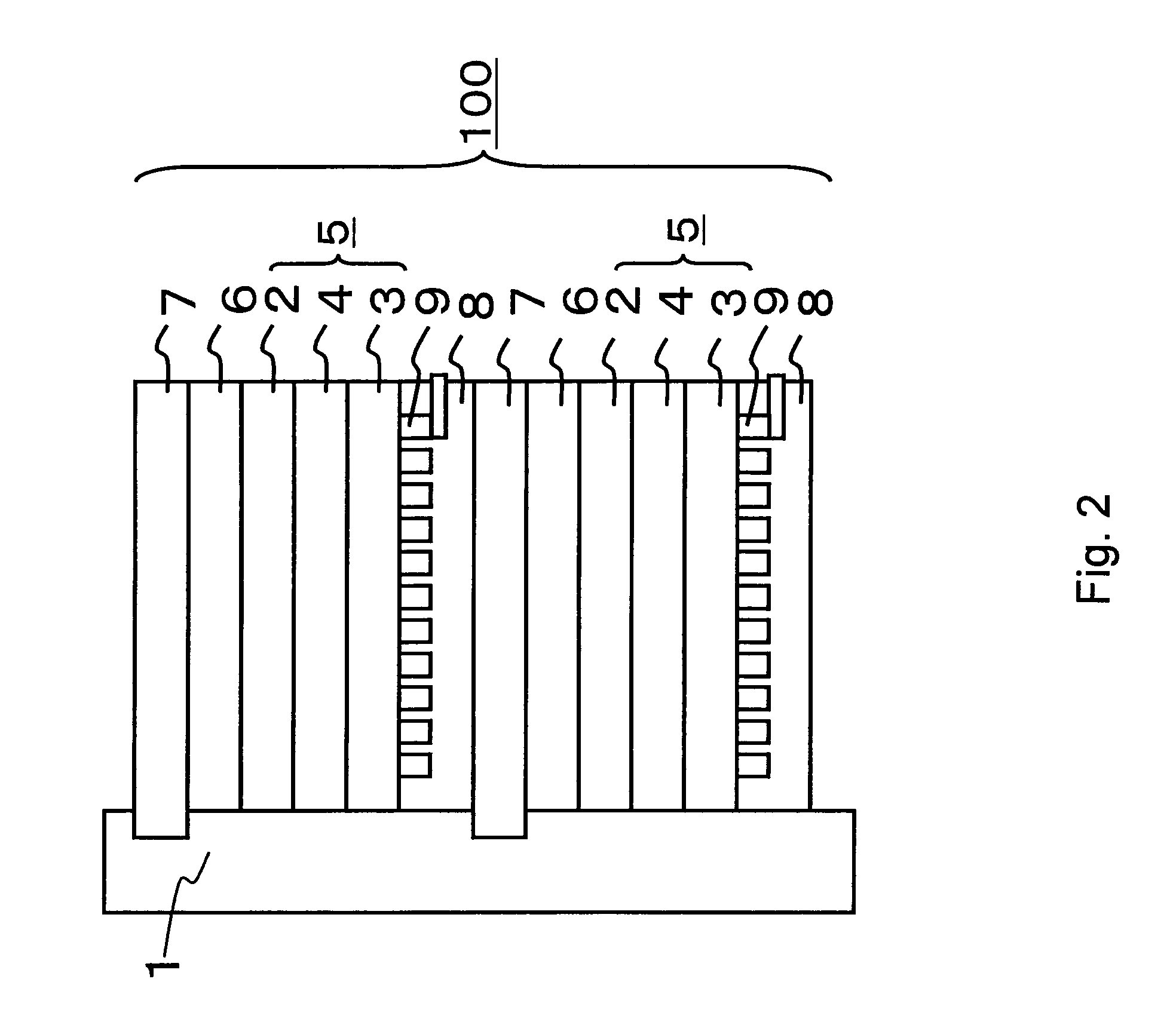
[0099]The fuel cell in the third embodiment will be described with reference to the accompanying drawings. FIG. 2 is a typical cross-sectional view of a fuel cell in the third embodiment of the present invention.

[0100]A stack 100 of a liquid fuel cell shown in FIG. 2 is formed by stacking a plurality of unit cells on top of each other. A fuel introduction path 1 is disposed on the side face of the stack 100. A liquid fuel is supplied into the fuel introduction path 1 from a liquid fuel tank (not shown) through an introduction pipe (not shown). The liquid fuel preferably contains methanol. For example, an aqueous methanol solution or methanol can be used as the liquid fuel. Each unit cell comprises a membrane electrode composition (electrogenic part) 5 comprising a fuel electrode (also known as an anode) 2, an oxidizer electrode (also known as a cathode) 3, and an electroly...


PUM

PropertyMeasurementUnit
volume resistivityaaaaaaaaaa
particle diameteraaaaaaaaaa

Abstract

A fuel cell, which can supply stable output even at elevated temperatures and can maintain its power generation performance over a long period of time, can be realized by an electrode for a fuel cell comprising a catalyst layer formed of a catalyst composite and a binder, the catalyst composite comprising a proton-conductive inorganic oxide and an oxidation-reduction catalyst phase supported on the proton-conductive inorganic oxide, the proton-conductive inorganic oxide comprising a catalyst carrier selected from tin(Sn)-doped In2O3, fluorine(F)-doped SnO2, and antimony(Sb)-doped SnO2 and an oxide particle phase chemically bonded to the surface of the catalyst carrier. The catalyst composite is manufactured by dispersing a catalyst carrier in a solution containing a material as a starting material for an oxide particle phase, heat treating the dispersion to form a proton-conductive inorganic oxide, further dispersing the proton-conductive inorganic oxide in a catalyst precursor-containing solution, and subjecting the dispersion to heat treatment or pH adjustment to deposit a catalyst phase.

Description

CROSS-REFERENCE TO RELATED APPLICATIONS[0001]This application is based upon and claims the benefit of priority from the prior Japanese Patent Applications No. 208241 / 2006, filed on Jul. 31, 2006; the entire contents of which are incorporated herein by reference.BACKGROUND OF THE INVENTION[0002]1. Field of the Invention[0003]The present invention relates to an electrode for a fuel cell, comprising a proton conductor, a membrane electrode composite, and a fuel cell comprising a membrane electrode composite. The present invention also relates to a method for manufacturing them.[0004]2. Background Art[0005]Fuel cells comprise a fuel electrode (anode) provided on one side of a proton-conductive film and an oxidizing agent (oxidizer) electrode (cathode) provided on the other side of the proton-conductive film. Upon the supply of a fuel such as hydrogen or methanol to the anode, the fuel is electrochemically oxidized in the anode to generate protons and electrons. The generated electrons f...

Claims


Application Information

Patent Timeline
Patent Type & Authority Patents(United States)
IPC IPC(8): H01M4/02H01M4/86H01M4/88H01M4/90H01M8/10
CPCH01M4/8647H01M4/8828H01M4/90H01M4/9041H01M4/9075H01M4/92H01M4/925H01M4/8652H01M4/8657H01M2008/1095Y02E60/50
Inventor TAMURA, JUNNAKANO, YOSHIHIKOMEI, WUMIKOSHIBA, SATOSHI
Owner KK TOSHIBA
Learn More