
Charged particle extraction device and method of design there for

a plasma and charge technology, applied in the direction of beam deviation/focusing, instruments, electric/magnetic means, etc., can solve the problems of unrealized plasma ion source, and unsatisfactory plasma ion source results, etc., to achieve the effect of high brightness

Active Publication Date: 2011-01-18
FEI CO
View PDF37 Cites 8 Cited by
  • Summary
  • Abstract
  • Description
  • Claims
  • Application Information

AI Technical Summary

Benefits of technology

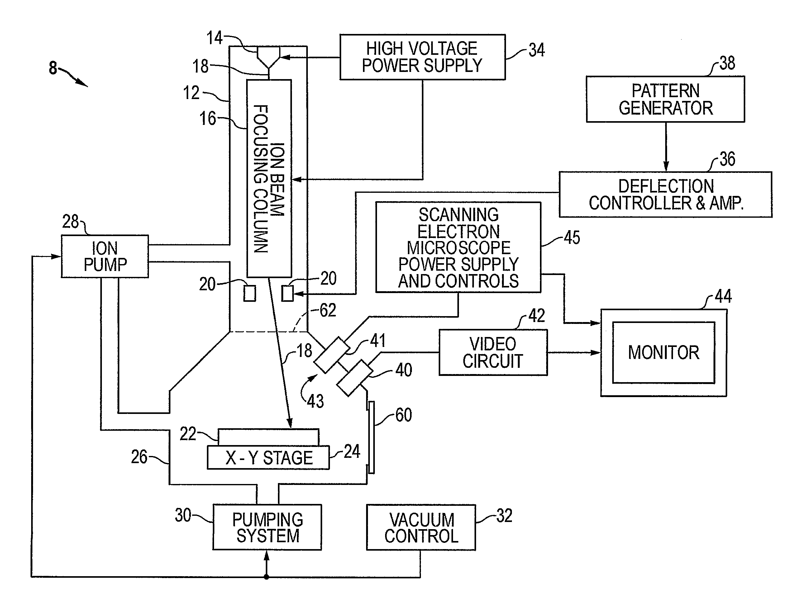
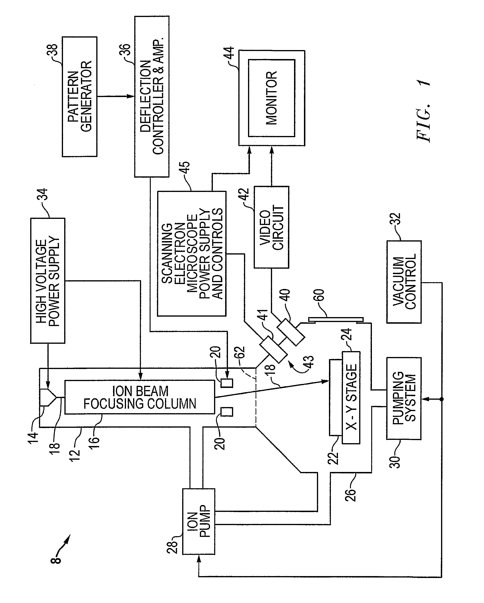
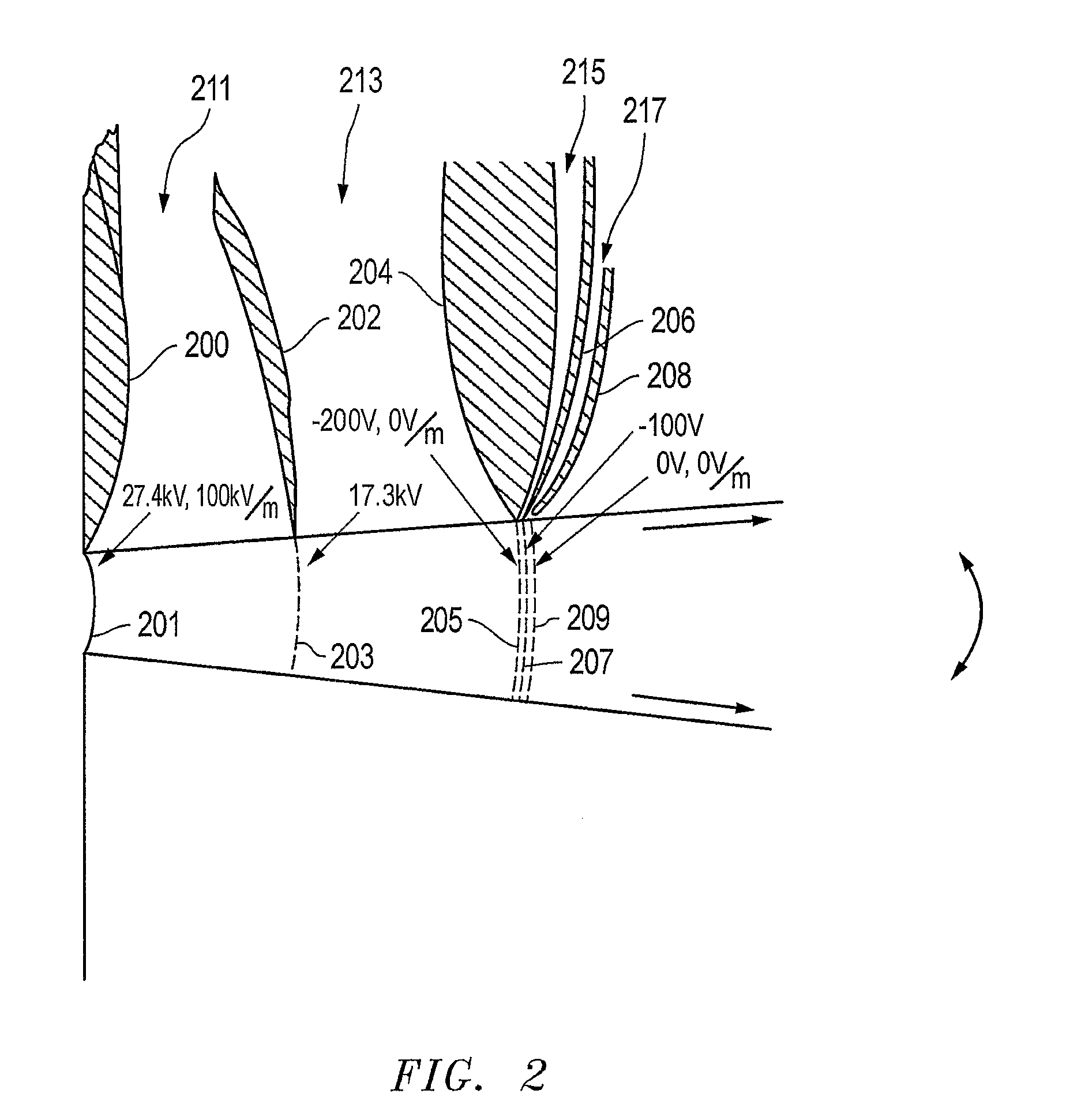
The present invention provides a method for designing an extraction device that can produce a charged particle beam with high brightness. The device uses a set of electrodes with apertures through which a beam is drawn from a charged particle source. The shapes and potentials applied to the electrodes are designed to create a low-emittance beam. The invention also ensures that there is no electric field in the vicinity of the aperture of the last electrode furthest from the particle source. The invention can be used as a basis for modifying or designing other structures for carrying out the same purposes.

Problems solved by technology

Though LMIS technology may present nanometer scale milling capability, it produces unwanted doping effects by introducing Gallium into a substrate or target.
But this has proved difficult and much research is devoted to improvement of extraction mechanisms to extract the ions from the plasma in the form of a beam.
Despite these efforts brightness in excess of 105 A / sr / m2 has not been achieved with a plasma ion source.

Method used


Image

  • Charged particle extraction device and method of design there for
  • Charged particle extraction device and method of design there for
  • Charged particle extraction device and method of design there for

Examples


example

Diverging Wedge Beam

[0172]For this example a 5° diverging beam is extracted through a 1 mill-meter (mm) wide, 1 meter (m) long rectangular slit. The plasma source is assumed to be a Krypton plasma of density 1013 cm−3 at the sheath edge, The total extraction energy is 20 kV and the total blocking potential is 200V.

[0173]Extraction Gap Stage 1

[0174]The problem can be considered analogous to that of a complete cylindrical diode of curvature re=5.737 mm The current density flowing across the meniscus yields B=7.6218·108 according to equation (12). The ratio of the sheath to the pre-sheath is given by first solving equation (6) for the boundary conditions set in equation (25):

[0175]β⁡(γm)=153492⁢Brm=1.71827×10⁻³(52)

and then solving equation (19) to find γm=1.71797×10⁻³. From equation (7) R=1.00172 so that the sheath width is given by:

(1.00172)rs−rs=9.9μm  (53)

[0176]The gradient at the sheath edge in terms of γm is:

[0177]ⅆVⅆγ⁢(γm=1.71827×10⁻³)=11644⁢⁢V⁢ / ⁢unit(54)

Since

[0178]γ=ln⁡(rrs),⁢d⁢...


PUM


Abstract

The present invention provides a method for extracting a charged particle beam from a charged particle source. A set of electrodes is provided at the output of the source. The potentials applied to the electrodes produce a low-emittance growth beam with substantially zero electric field at the output of the electrodes.

Description

TECHNICAL FIELD OF THE INVENTION[0001]The present invention relates to the extraction of a charged particle beam from a plasma. The invention is particularly directed toward the extraction of high brightness beams.BACKGROUND OF THE INVENTION[0002]There exist a range of applications for ion beams particularly in the semiconductor industry. For example, the fabrication and correction of lithography masks involves sub-micron etching capability. This is currently achieved using medium-energy particle beams (10-50 kilo-electron-Volts (keV)), commonly referred to as Focused Ion Beams (FIB). To enable sub-micron feature creation, the FIB must be capable of focus down to a nanometer scale spot size. This requires the extraction of very high brightness beams in excess of 105 Angstroms per steradian per meter squared (A / sr / m2).[0003]Liquid Metal Ion Source (LMIS) technology has been capable of this level of brightness for many years. The technology exploits the capillary effect of liquid Gall...

Claims


Application Information

Patent Timeline
Patent Type & Authority Patents(United States)
IPC IPC(8): H01J27/00G21KH01J37/08
CPCH01J27/024H01J37/08H01J3/00H01J2237/061H01J2237/083H01J2237/121H01J2237/31749
Inventor BOSWELL, RODERICKSUTHERLAND, ORSON
Owner FEI CO
Learn More