Apparatus and process for generating, accelerating and propagating beams of electrons and plasma

a technology of electrons and plasma, applied in the direction of electric discharge lamps, nanotechnology, discharging tube hollow cathodes, etc., can solve the problems of insufficient current density that can be achieved in this manner, insufficient effect, and high quantity of instruments required, and achieve the effect of high energy density

Inactive Publication Date: 2011-01-18
MATACOTTA FRANCESCO CINO +1
View PDF6 Cites 14 Cited by
  • Summary
  • Abstract
  • Description
  • Claims
  • Application Information

AI Technical Summary

Benefits of technology

[0013]The aim of the present invention is therefore to eliminate the drawbacks noted above in known types of apparatuses and processes for generating, accelerating and propagating beams of charged particles, by providing an apparatus and a process which allow to obtain a beam of electrons and plasma with a higher energy density in the beam with respect to the energy supplied to the system.

Problems solved by technology

The current densities that can be achieved in this manner, however, are not sufficient for some applications.
Although in this manner it is possible to obtain, in this low-pressure area, electron currents with a high current density, the quantity of instruments required is very high and the effect is not satisfactory.
The generation of the beam of electrons with the pseudo-spark chamber is technically complicated, since it is also limited as regards beam power and beam divergence.
Although this device is effective, some problems and limitations are observed, including the fact that part of the useful energy of the capacitors is used to supply the predischarge in the air gap across resistors (11).
Moreover, the discharge time is determined by the release of the spark in the air gap, and this depends on several factors which cannot be controlled, such as the microscopic cleanness of the points (12) of the air gap, the composition, pressure and especially the humidity of the ambient air, and cannot be predetermined accurately.
Moreover, the pressure in the vacuum chamber must be kept within an extremely limited range.

Method used


Image

  • Apparatus and process for generating, accelerating and propagating beams of electrons and plasma
  • Apparatus and process for generating, accelerating and propagating beams of electrons and plasma
  • Apparatus and process for generating, accelerating and propagating beams of electrons and plasma

Examples


Embodiment Construction

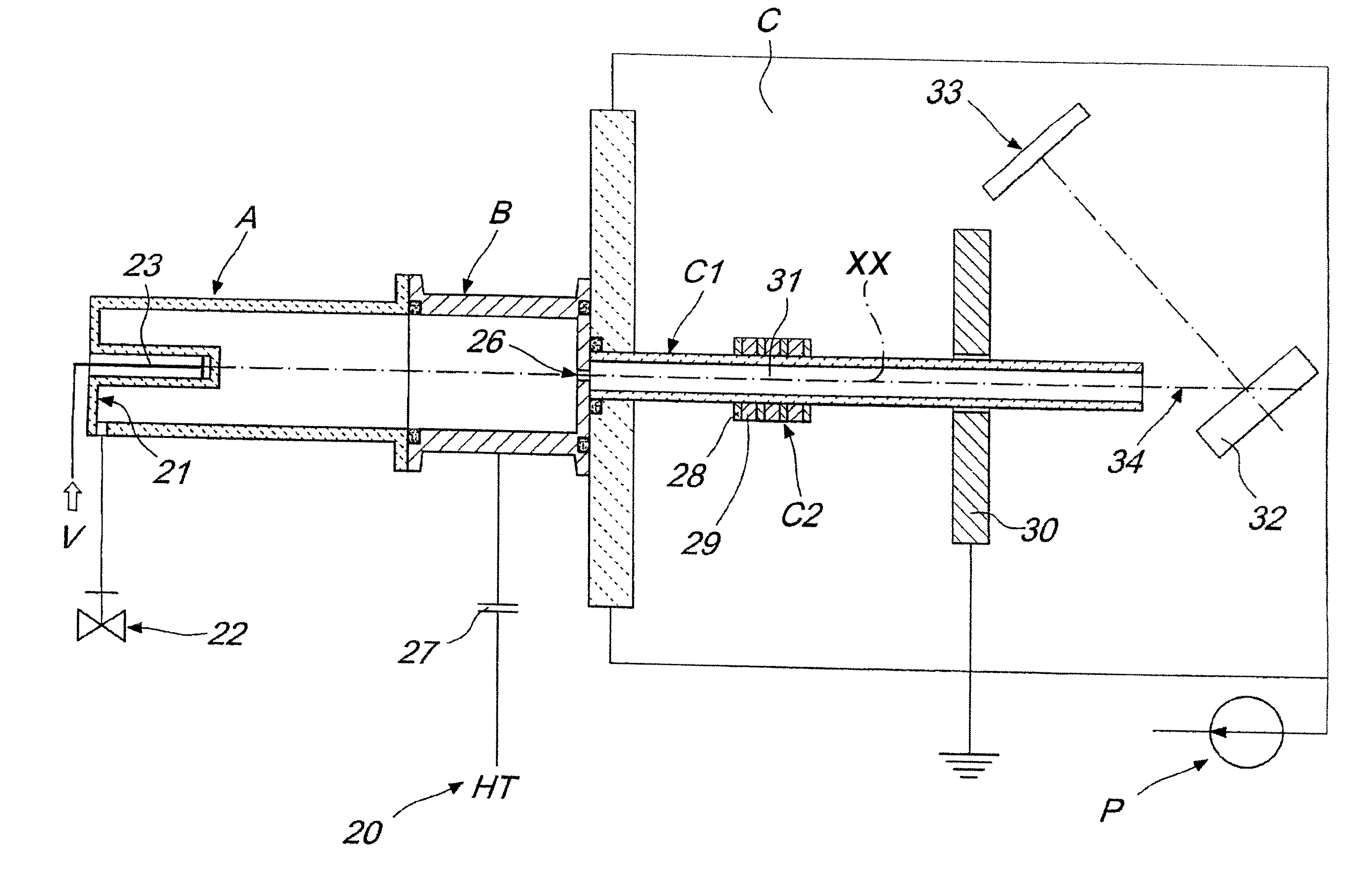
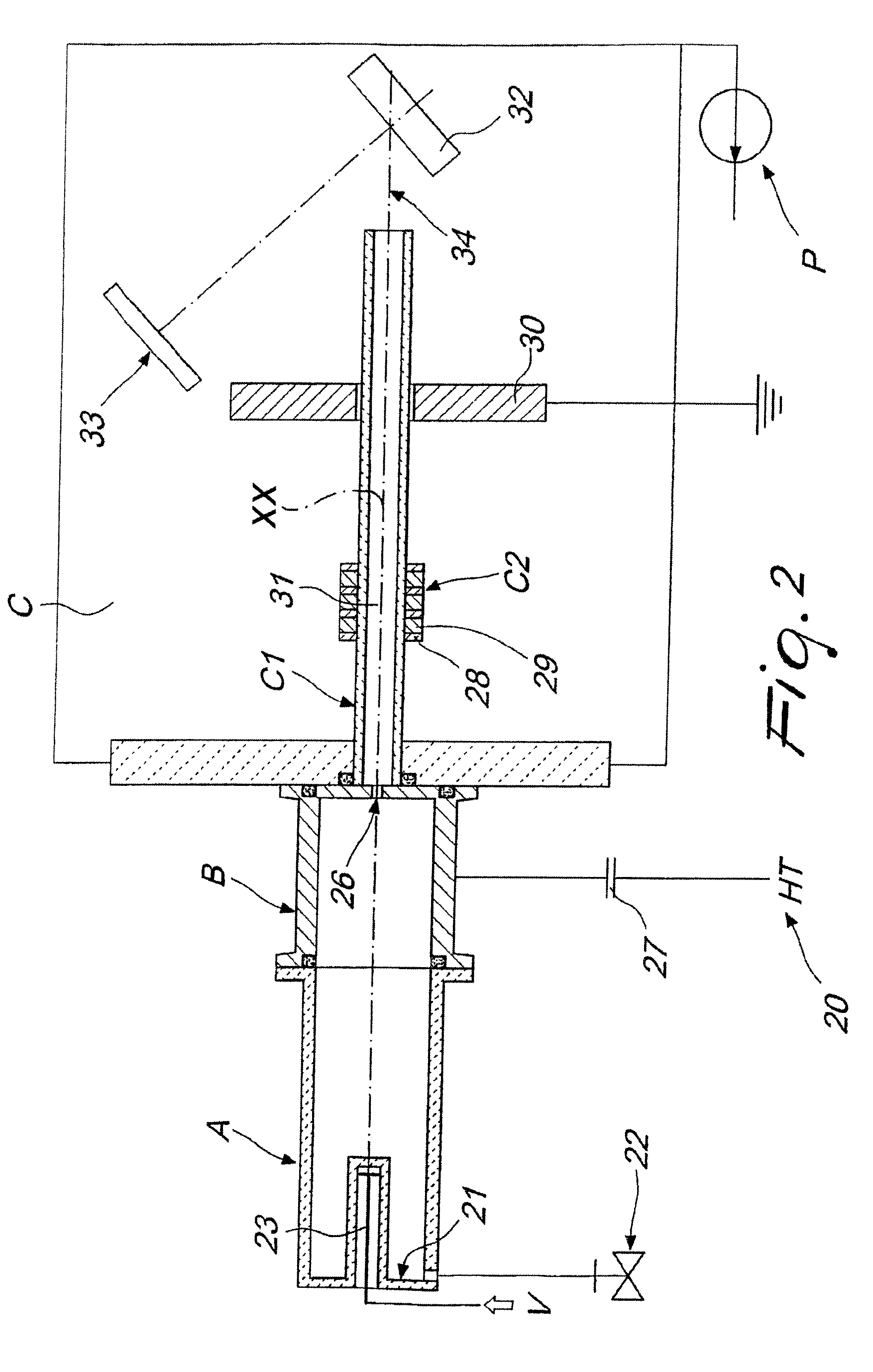
[0050]With reference to FIGS. 2 to 3, the apparatus (20) comprises a discharge tube A for the plasma, which is made of glass or other dielectric material. This tube has the main purpose of containing an amount of gas which is sufficient to supply the number of ions required to trigger and maintain the main electrical discharge in a hollow cathode B which is connected hermetically thereto.

[0051]The pressure of the gas at the bottom (21) of the tube A is maximum with respect to the pressures that occur in the other parts of the apparatus. By means of a needle valve (22), which is connected to the tube (A), and upstream of which the pressure is equal to, or greater than, the atmospheric value, a stream of gas is in fact generated which flows from the bottom (21) of the tube A, through the hollow cathode B, enters a second dielectric tube C1 and then enters the deposition chamber C, which is connected hermetically to the cathode and downstream of which there are gas evacuation means, wh...


PUM


Abstract

An apparatus and a process for generating, accelerating and propagating beams of electrons and plasma at high density, the apparatus comprising: a first dielectric tube, which contains gas; a hollow cathode, which is connected to said first dielectric tube; a second dielectric tube, which is connected to said hollow cathode and protrudes inside, and is connected to, a deposition chamber; an anode, which is arranged around said second dielectric tube, in an intermediate position; means for applying voltage to said cathode and said anode; means for evacuating the gas from the chamber; and means for spontaneous conversion of gas in the first dielectric tube into plasma.

Description

[0001]The present invention relates to an apparatus and a process for generating, accelerating and propagating beams of electrons and plasma, particularly for applications in further methods for processing materials, for example for methods for depositing films or forming nanoclusters of various materials.BACKGROUND OF THE INVENTION[0002]More precisely, the present invention relates to the generation, acceleration and propagation of pulsed beams of electrons and plasma, which, when directed against targets made of solid or liquid matter, allow to obtain an explosive expulsion of small amounts of matter, a phenomenon known as ablation. It is believed, without intending to be constrained by any mechanism, that this phenomenon is linked to the release of energy carried by the beam not to the surface of the target but below it, so as to produce the explosion of the portion of material that lies below the surface.[0003]It is known in the background art to produce currents of electrons in...

Claims


Application Information

Patent Timeline
Patent Type & Authority Patents(United States)
IPC IPC(8): H01J17/26
CPCH01J1/025H01J3/025H05H1/54B82Y30/00
Inventor MATACOTTA, FRANCESCO CINO
Owner MATACOTTA FRANCESCO CINO
Why Eureka
Try Eureka