Tip turbine engine comprising turbine blade clusters and method of assembly

a turbine blade and cluster technology, applied in the direction of blade accessories, machines/engines, waterborne vessels, etc., can solve the problems of reducing and reducing the efficiency of the turbine, so as to reduce the leakage between adjacent blade platforms , the effect of increasing the rigidity of the turbin

Active Publication Date: 2011-01-25
RTX CORP
View PDF150 Cites 10 Cited by
  • Summary
  • Abstract
  • Description
  • Claims
  • Application Information

AI Technical Summary

Benefits of technology

[0008]The fan-turbine rotor assembly according to the present invention includes one or more turbine ring rotors. Each turbine ring rotor includes a multitude of turbine blade clusters defined about the engine centerline and mounted to a diffuser of the fan-turbine rotor. By forming the turbine blades in clusters, leakage between adjacent blade platforms is minimized which increases engine efficiency.
[0009]Assembly of the turbine blade clusters to an diffuser includes axial installation along an engine axis such that segmented attachment lugs are passed through a segmented aft slot surface of an engine base surface. The turbine blade clusters are then rotated about the engine axis to radially position the segmented attachment lugs adjacent the segmented aft slot surface lugs to radially and axially retain the turbine blade cluster to the engine base surface. Each cluster is rotated toward a radial stop in a direction which will maintain the turbine ring rotor against the radial stop during operation of the fan-turbine rotor assembly. A multitude of turbine rotor ring stages may also be locked together to further increase the rigidity of the turbine.
[0010]The present invention therefore provides a turbine blade cluster for a fan-turbine rotor assembly, which is readily manufactured and mountable to the outer periphery of a bypass fan.

Problems solved by technology

The axial flow relationship results in a relatively complicated elongated engine structure of considerable longitudinal length relative to the engine diameter.
This elongated shape may complicate or prevent packaging of the engine into particular applications.
Integrating the turbine onto the tips of the hollow bypass fan blades provides an engine design challenge.

Method used


Image

  • Tip turbine engine comprising turbine blade clusters and method of assembly
  • Tip turbine engine comprising turbine blade clusters and method of assembly
  • Tip turbine engine comprising turbine blade clusters and method of assembly

Examples


Embodiment Construction

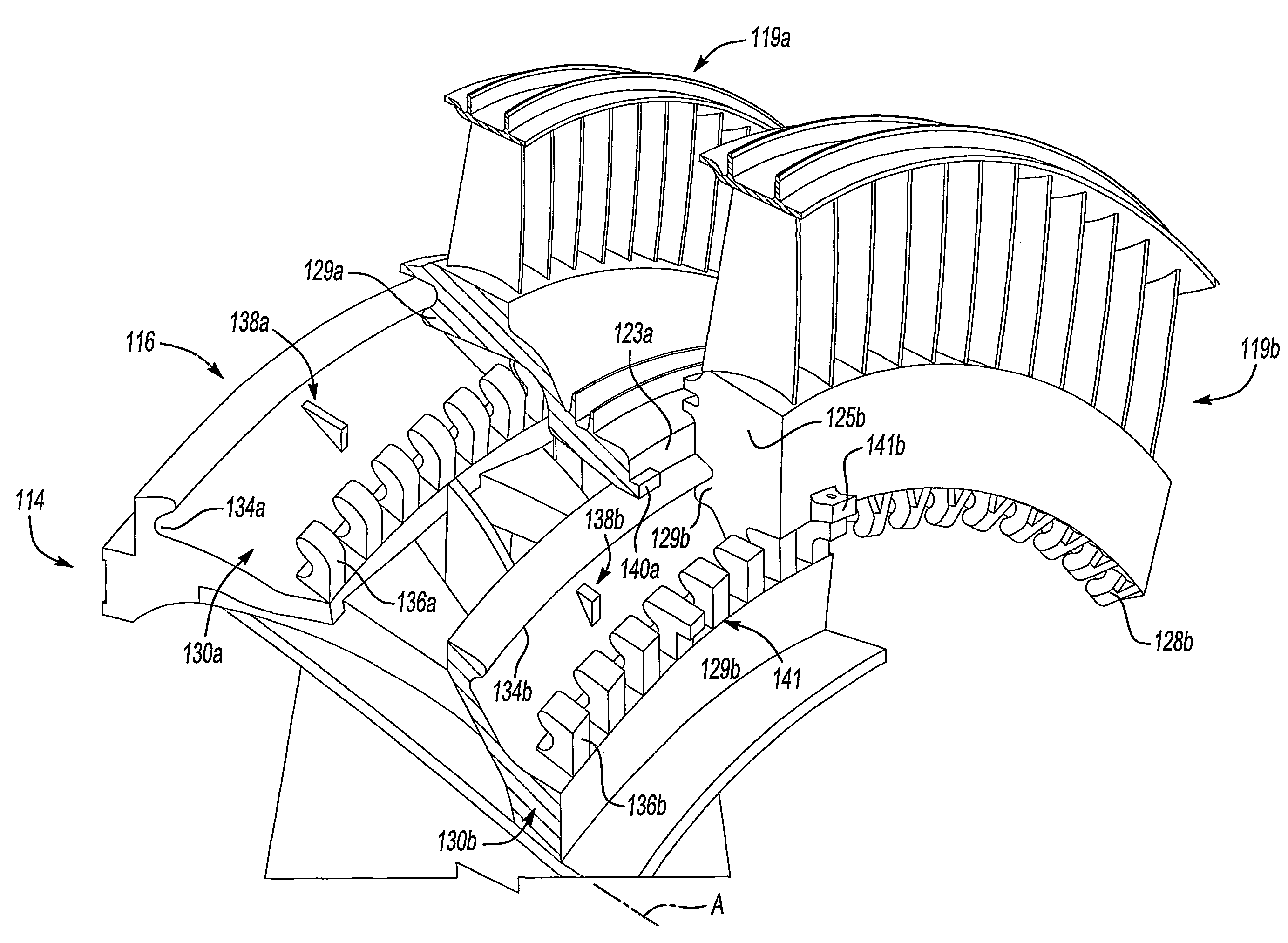
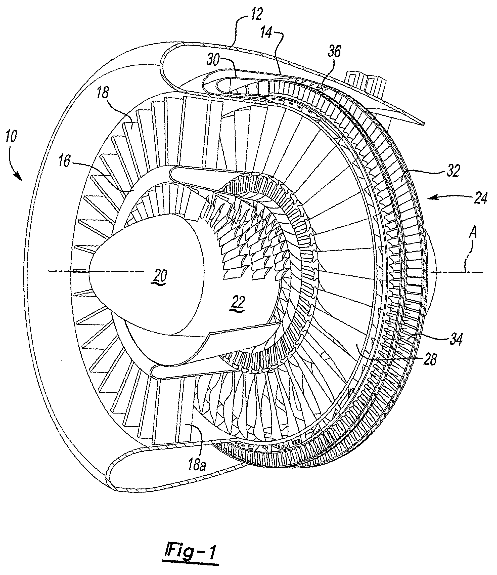
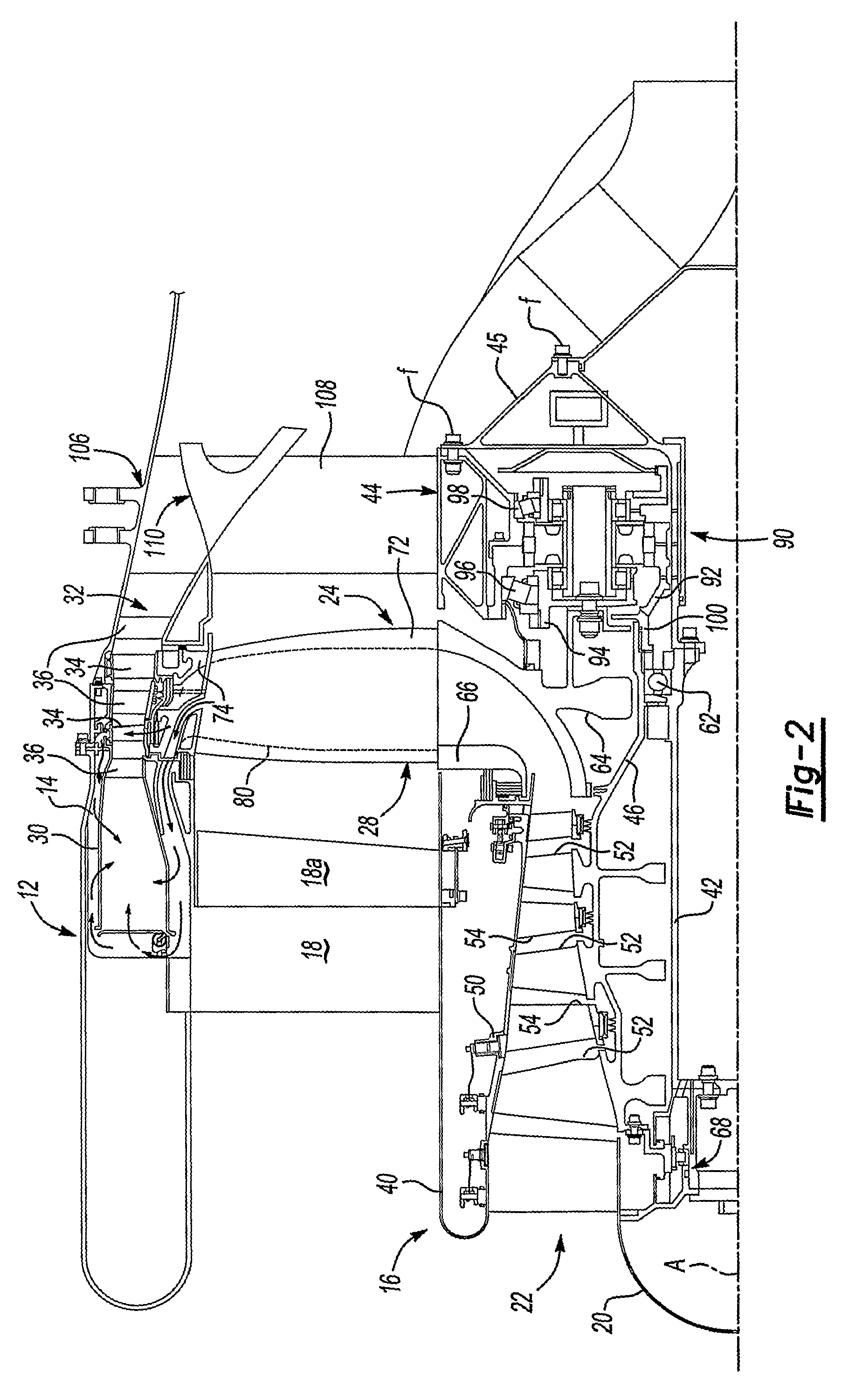
[0030]FIG. 1 illustrates a general perspective partial sectional view of a tip turbine engine type gas turbine engine 10. The engine 10 includes an outer nacelle 12, a nonrotatable static outer support structure 14 and a nonrotatable static inner support structure 16. A multitude of fan inlet guide vanes 18 are mounted between the static outer support structure 14 and the static inner support structure 16. Each inlet guide vane preferably includes a variable trailing edge 18A.

[0031]A nose cone 20 is preferably located along the engine centerline A to smoothly direct airflow into an axial compressor 22 adjacent thereto. The axial compressor 22 is mounted about the engine centerline A behind the nose cone 20.

[0032]A fan-turbine rotor assembly 24 is mounted for rotation about the engine centerline A aft of the axial compressor 22. The fan-turbine rotor assembly 24 includes a multitude of hollow fan blades 28. The hollow fan blades 28 communicate this compressed air from the axial compr...


PUM

PropertyMeasurementUnit
pressureaaaaaaaaaa
energyaaaaaaaaaa
diameteraaaaaaaaaa

Abstract

A tip turbine engine comprises a fan-turbine rotor assembly that includes one or more turbine ring rotors. Each turbine ring is assembled from a multitude of turbine blade clusters. Assembly of a multitude of turbine blade clusters to a diffuser includes axial installation and radial rotation. The clusters are axially installed, then rotated toward a radial stop in a direction which will maintain each cluster against the radial stop during operation of the fan-turbine rotor assembly. A multitude of turbine rotor ring stages may also be locked together to future increase the rigidity of the turbine.

Description

BACKGROUND OF THE INVENTION[0001]The present invention relates to a gas turbine engine, and more particularly to the attachment of a tip turbine ring rotor upon a bypass fan of a tip turbine engine.[0002]An aircraft gas turbine engine of the conventional turbofan type generally includes a forward bypass fan a compressor, a combustor, and an aft turbine all located along a common longitudinal axis. A compressor and a turbine of the engine are interconnected by a shaft. The compressor is rotatably driven to compress air entering the combustor to a relatively high pressure. This pressurized air is then mixed with fuel in a combustor and ignited to form a high energy gas stream. The gas stream flows axially aft to rotatably drive the turbine which rotatably drives the compressor through the shaft. The gas stream is also responsible for rotating the bypass fan. In some instances, there are multiple shafts or spools. In such instances, there is a separate turbine connected to a separate c...

Claims


Application Information

Patent Timeline
Patent Type & Authority Patents(United States)
IPC IPC(8): F01D5/30
CPCF01D5/225F01D5/3007F02C3/073F02K3/068F02C3/08Y10T29/49321F05D2260/30
Inventor SUCIU, GABRIEL L.NORRIS, JAMES W.NORDEEN, CRAIG A.
Owner RTX CORP
Why Eureka
Try Eureka