Light source module, light source apparatus and liquid crystal display

a technology of light source apparatus and light source module, which is applied in the direction of lighting and heating apparatus, lighting support devices, instruments, etc., can solve the problems of difficult to obtain uniform luminance and large irregular luminance of white light obtained by mixing color rays, so as to reduce layout intervals, enhance uniformity, and restrain color differences

Inactive Publication Date: 2011-02-01
SONY CORP
View PDF19 Cites 12 Cited by
  • Summary
  • Abstract
  • Description
  • Claims
  • Application Information

AI Technical Summary

Benefits of technology

[0012]Thus, there is a need for a light source module, a light source apparatus, and a liquid crystal display, with which it is possible to obtain a more uniform luminance and to enhance the heat radiating property for LED devices.
[0014]In the light source module based on an embodiment of the present invention, bare chips of light emitting diodes (LED chips) are used as the LED devices, so that it is possible to reduce the layout intervals between the LEDs for the colors, to restrain the color difference and to enhance the uniformity of luminance. In this case, the LED chips for the RGB colors may be located respectively on the vertices of a triangle so that the intervals between the chips are substantially equal, whereby the mixing quality of the RGB color rays can be enhanced, and uniform white light can be obtained.
[0016]Furthermore, in the light source module based on an embodiment of the present invention, the surface on one side of the wiring board is made to be a device forming surface, and the surface on the other side of the wiring board is made to be a heat radiating surface. This configuration makes it possible to enhance the mounting efficiencies of the LED chips and the external connecting terminal on the wiring board, to enhance the degree of freedom in laying around the wiring pattern on the wiring board, simultaneously to enhance the heat radiating efficiency for the device forming surface, and to thereby prevent variations in chip characteristics, a lowering in device lifetime, and a rise in the temperature inside the backlight.
[0017]As above-mentioned, according to an embodiment of the present invention, it is possible to contrive simultaneously a more uniform luminance of white light and an enhanced heat radiating property. This makes it possible to fabricate a planar light source apparatus suitable for use as a backlight apparatus for a liquid crystal display, for example.

Problems solved by technology

However, in the light source apparatus described in Patent Document 1, the LED devices for the RGB colors are arranged in a row, so that the intervals between the LED devices for the colors are not constant; therefore, irregularities in the luminance of the white light obtained by mixing the color rays are comparatively large.
Therefore, it is difficult to dispose the LED devices for colors close to each other and, therefore, it is difficult to obtain a uniform luminance.

Method used


Image

  • Light source module, light source apparatus and liquid crystal display
  • Light source module, light source apparatus and liquid crystal display
  • Light source module, light source apparatus and liquid crystal display

Examples


Embodiment Construction

[0031]Now, some embodiments of the present invention will be described below, referring to the drawings.

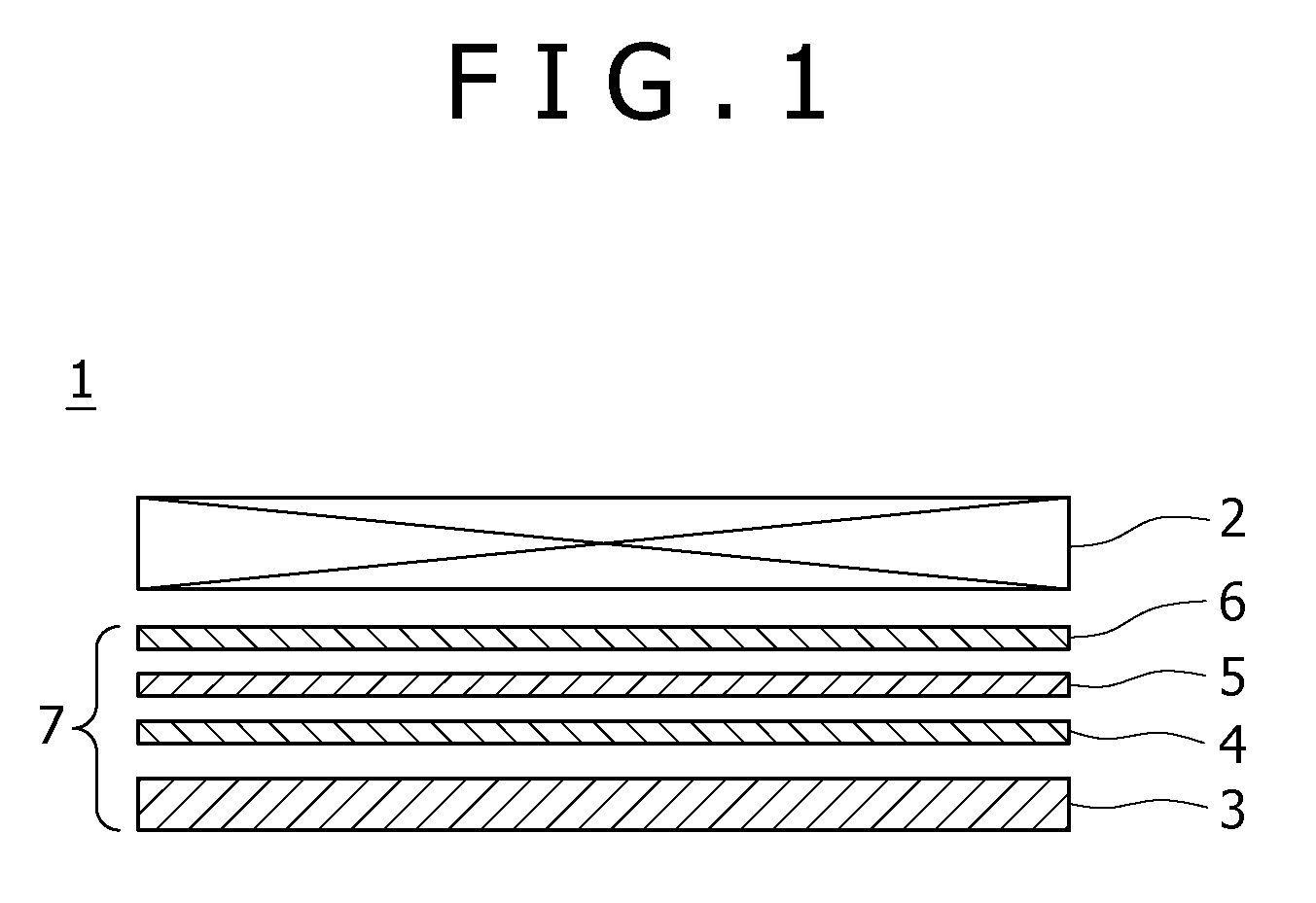
[0032]FIG. 1 is a side sectional view showing a general configuration of a liquid crystal display 1 according to an embodiment of the present invention. The liquid crystal display 1 shown in FIG. 1 includes a liquid crystal display panel 2, and a backlight apparatus 7 which is disposed on the back side (in FIG. 1, the lower side) of the liquid crystal display panel 2 and is operative to illuminate the back side of the liquid crystal display panel 2.

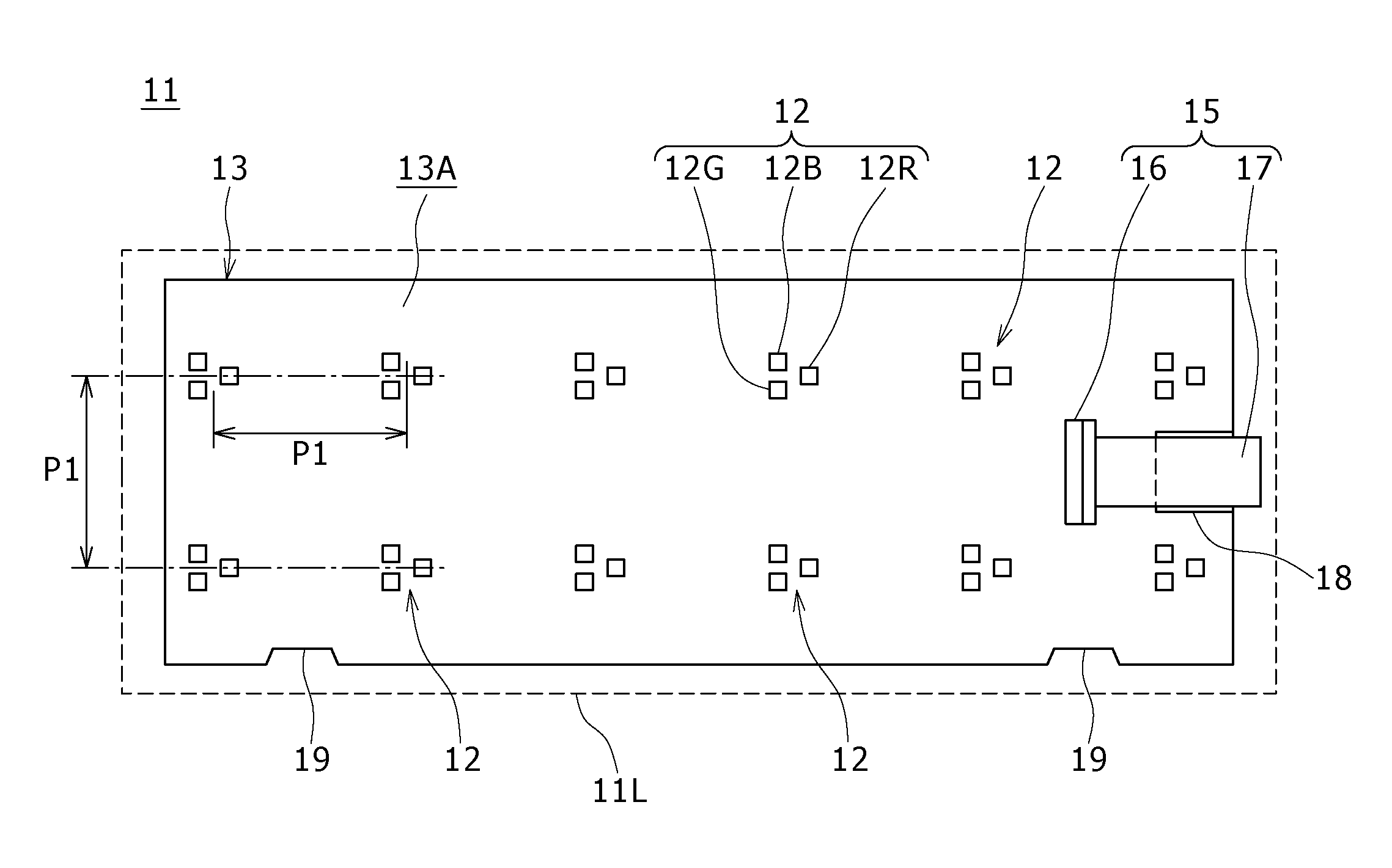
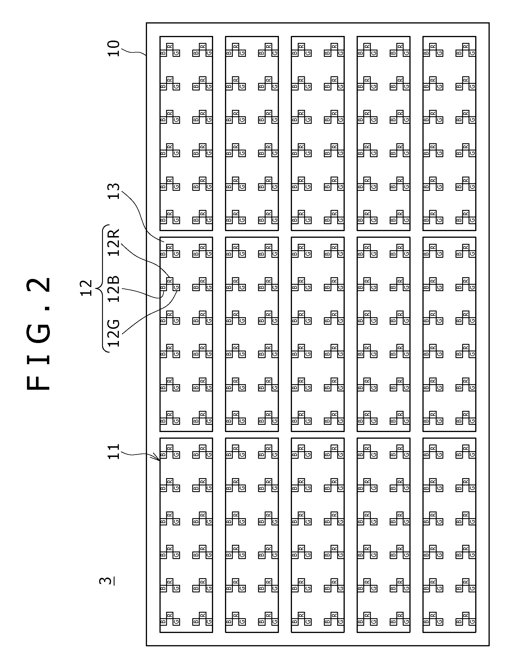
[0033]The backlight apparatus 7 has an underneath-type backlight unit (light source apparatus) 3 using light emitting diodes (LEDs) as light sources, and has a configuration in which a diffuser plate 4, a luminance enhancing sheet 5, and a polarized light separating element 6 are disposed in appropriate combination on the light outgoing surface side of the backlight unit 3.

[0034]The liquid crystal display panel 2 includes a pair of tran...


PUM


Abstract

A light source module includes a light emitting diode and a wiring board. The light emitting diode (LED) chip group includes LED chips for red, green and blue colors. A plurality of the LED chip groups are mounted on the wiring board. A surface on one side of the wiring board is a device forming surface including the plurality of the LED chip groups, an external connecting terminal for leading out electrodes, and a wiring pattern for electrical connection between the LED chip groups and the external connecting terminal. A surface on the other side of the wiring board is a heat radiating surface which is thermally connected to the device forming surface and operative to radiate heat generated at the device forming surface to the exterior.

Description

CROSS REFERENCES TO RELATED APPLICATIONS[0001]The present invention contains subject matter related to Japanese Patent Application JP 2006-199437 filed with the Japan Patent Office on Jul. 21, 2006, the entire contents of which being incorporated herein by reference.BACKGROUND OF THE INVENTION[0002]1. Field of the Invention[0003]The present invention relates to a light source module, a light source apparatus and a liquid crystal display, using light emitting diodes (LEDs) as light sources.[0004]2. Description of the Related Art[0005]Liquid crystal displays (LCDs) are lower in power consumption than cathode ray tubes (CRTs), and can be reduced in size and in thickness. At present, liquid crystal displays in various sizes are widely used for apparatuses ranging from small ones such as portable phones, digital cameras, PDA (Personal Digital Assistants), etc. to large-sized liquid crystal TV sets.[0006]The liquid crystal displays are classified into the transmission type, the reflection...

Claims


Application Information

Patent Timeline
Patent Type & Authority Patents(United States)
IPC IPC(8): F21V21/00F21V29/00H01L33/62H01L33/64
CPCG02F1/133603H01L24/45G02F1/133608G02F1/133609G02F1/133611G02F1/133621H05K1/0209F21K9/00H01L2924/00014H01L2924/01006H01L2924/01015H01L2224/45G02F2001/133612G02F2001/133628H05K2201/09318H05K2201/09681H05K2201/09781H05K2201/10106H01L2924/00H01L2224/48H01L2924/00011H01L2924/181H01L2924/12041G02F1/133612G02F1/133628H01L2224/45099H01L2224/43G02F1/1335
Inventor FUJINO, TOYOMIFUKASAWA, HIROYUKIFUJII, MASARU
Owner SONY CORP
Why Eureka
Try Eureka