Burner assembly with screen

a technology of burner assembly and burner body, which is applied in the direction of combustion types, lighting and heating apparatuses, and combustion using lump and pulverulent fuel, etc. it can solve the problems of increasing the amount of labor required to operate the burner, increasing the cost of manufacture and maintenance, and affecting the combustion efficiency of the burner. , to achieve the effect of short flame length, rapid combustion and improved combustion intensity

Active Publication Date: 2011-02-01
ASTEC
View PDF3 Cites 5 Cited by
  • Summary
  • Abstract
  • Description
  • Claims
  • Application Information

AI Technical Summary

Benefits of technology

[0004]Accordingly, it is an advantage of the invention described and claimed herein to provide an apparatus capable of selectively firing on gaseous fuel, liquid fuel, or both gaseous and liquid fuel. It is also an advantage of the invention described and claimed herein to provide an apparatus capable of firing on gaseous and / or liquid fuels without physically altering the components of the apparatus, changing the firing rate of the apparatus, or shutting down the apparatus. It is a further advantage of the invention described and claimed herein to provide an apparatus adapted to fire on oil or liquid propane without changing the atomizing nozzle. It is another advantage of the invention described and claimed herein to provide an apparatus that is capable of supplying natural gas or propane to the atomizing nozzle for use as pilot fuel. It is also an advantage of the invention described and claimed herein to provide an apparatus for producing a stable main flame configuration that has a short flame length and a narrow flame diameter. It is also an advantage of the invention described and claimed herein to provide an apparatus for producing a main flame configuration that is adapted for use on a wide variety of different-sized combustion chambers having different-sized combustion spaces. It is another advantage of the invention described and claimed herein to provide an apparatus that more rapidly, completely, and uniformly mixes fuel and air, thereby providing a more rapid combustion, improving combustion intensity, reducing the combustion space required in the asphalt drum, and reducing CO emissions in the combustion space. It is yet another advantage of a preferred embodiment of the invention described and claimed herein to reduce NOx emissions.
[0005]It is a further advantage of the invention described and claimed herein to provide an apparatus having the capability of firing on low excess air pre-mix gas. It is a still further advantage of the invention described and claimed herein to provide an apparatus for producing a stabilizing gas base flame. It is still another advantage of the invention described and claimed herein to provide an apparatus that reduces the temperature of the dryer drum breech plate. It is a further advantage of the invention described and claimed herein to provide an apparatus that eliminates the need for adjustable spin vanes in order to achieve a desired flame configuration. It is another advantage of the invention described and claimed herein to provide an apparatus having improved aerodynamics which reduce energy consumption and body pressure and produce a more free flowing burner assembly. It is still another advantage of the invention described and claimed herein to provide an apparatus which produces reduced noise levels during operation. It is yet another advantage of the invention described and claimed herein to provide an apparatus that is less complicated and expensive to manufacture, operate and maintain than conventional burner assemblies.
[0006]Additional advantages of the invention will become apparent from an examination of the drawings and the ensuing description.EXPLANATION OF TECHNICAL TERMS
[0007]As used herein, the term “mounted about the periphery of the housing” means that the at least one pre-mix gas injection nozzle is mounted within the interior of the housing of the burner assembly such that the nozzles do not extend to center of housing. More particularly, the term “mounted about the periphery of the housing” means that the at least one pre-mix gas injection nozzle is mounted within the interior of the housing of the burner assembly such that the nozzles leave an open area in the center of the housing through which the primary air tube, the pilot assembly and the like may pass unimpeded.
[0008]As used herein, the term “centrally located in the housing” means that the pilot assembly is located and arranged in the housing of the burner assembly such that it passes through the open area in the center of the housing produced by the arrangement of the pre-mix gas injection nozzles.
[0009]As used herein, the term “screen” refers to any structure, mechanism, device or combination adapted to alter or change the directional flow of fluid in the housing of the burner assembly. The term “screen” includes, but is not limited to, coarse wire mesh constructions, large sieve structures and riddle-like devices.SUMMARY OF THE INVENTION

Problems solved by technology

However, conventional burner assemblies suffer from several disadvantages.
For example, conventional burner assemblies are incapable of producing a flame configuration satisfactory for asphalt production in a variety of different-sized combustion chambers.
Adjustable spin vanes, however, increase the cost of manufacture and maintenance, and the amount of labor required to operate the burner.

Method used


Image

  • Burner assembly with screen
  • Burner assembly with screen
  • Burner assembly with screen

Examples


Embodiment Construction

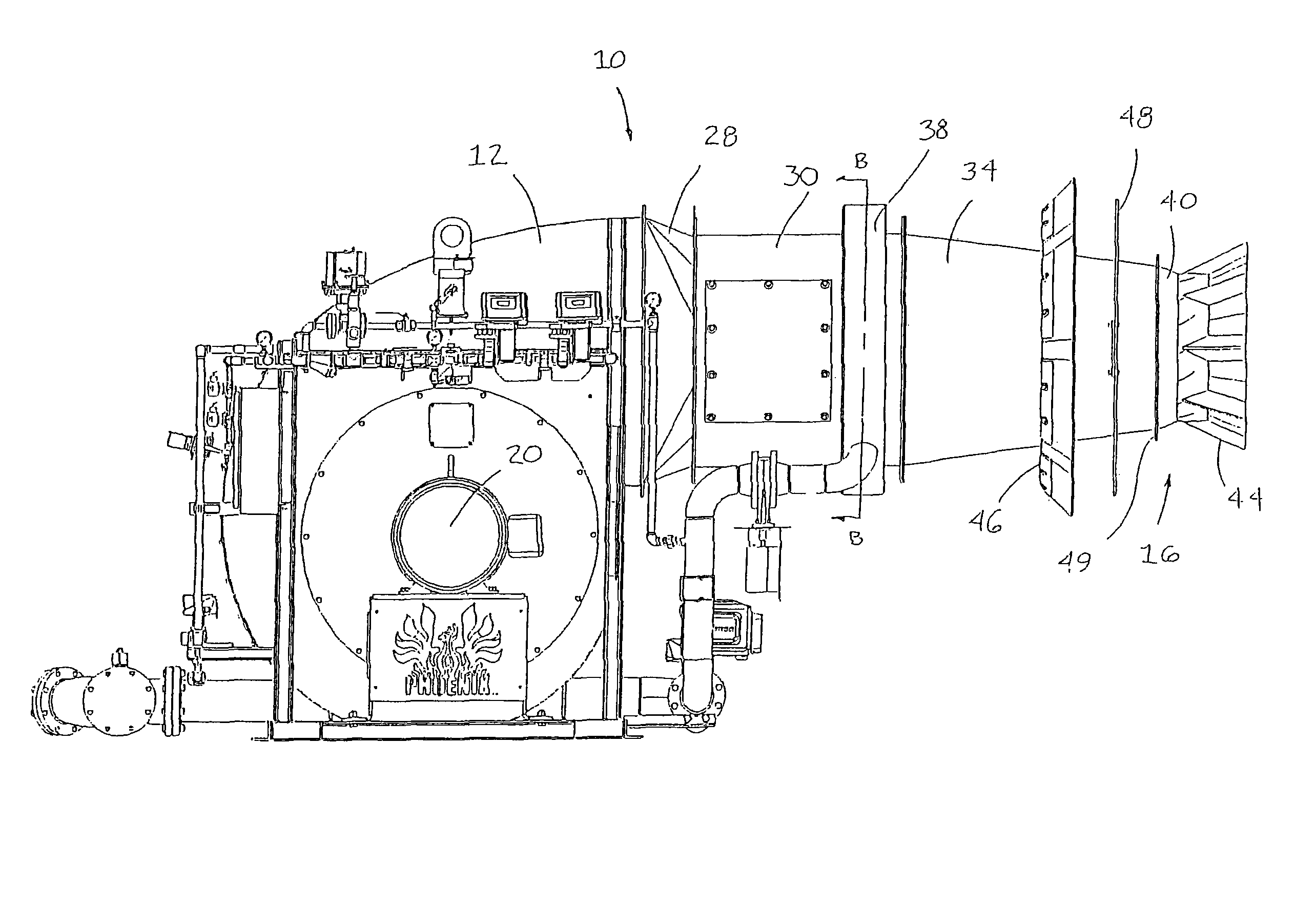
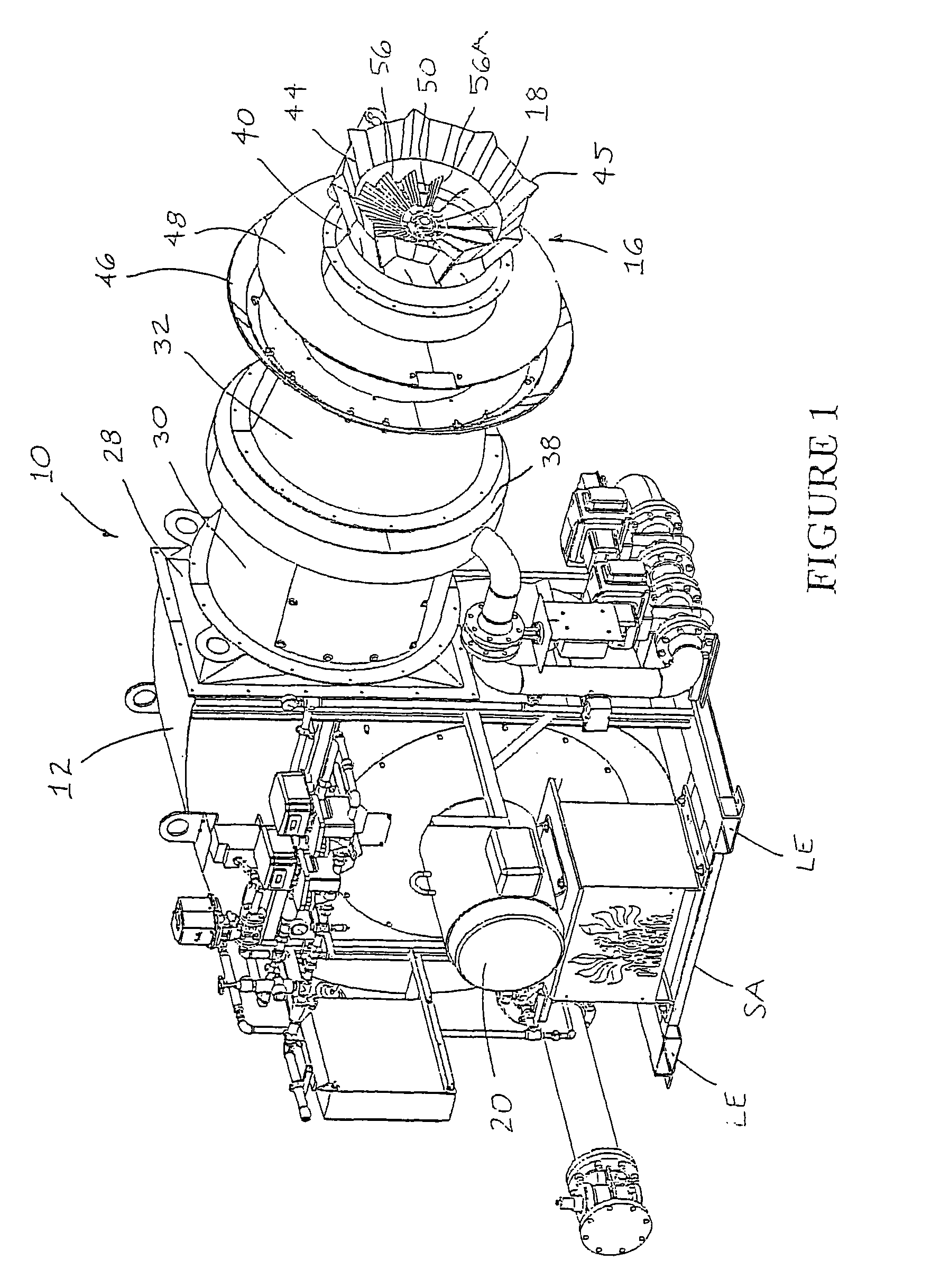
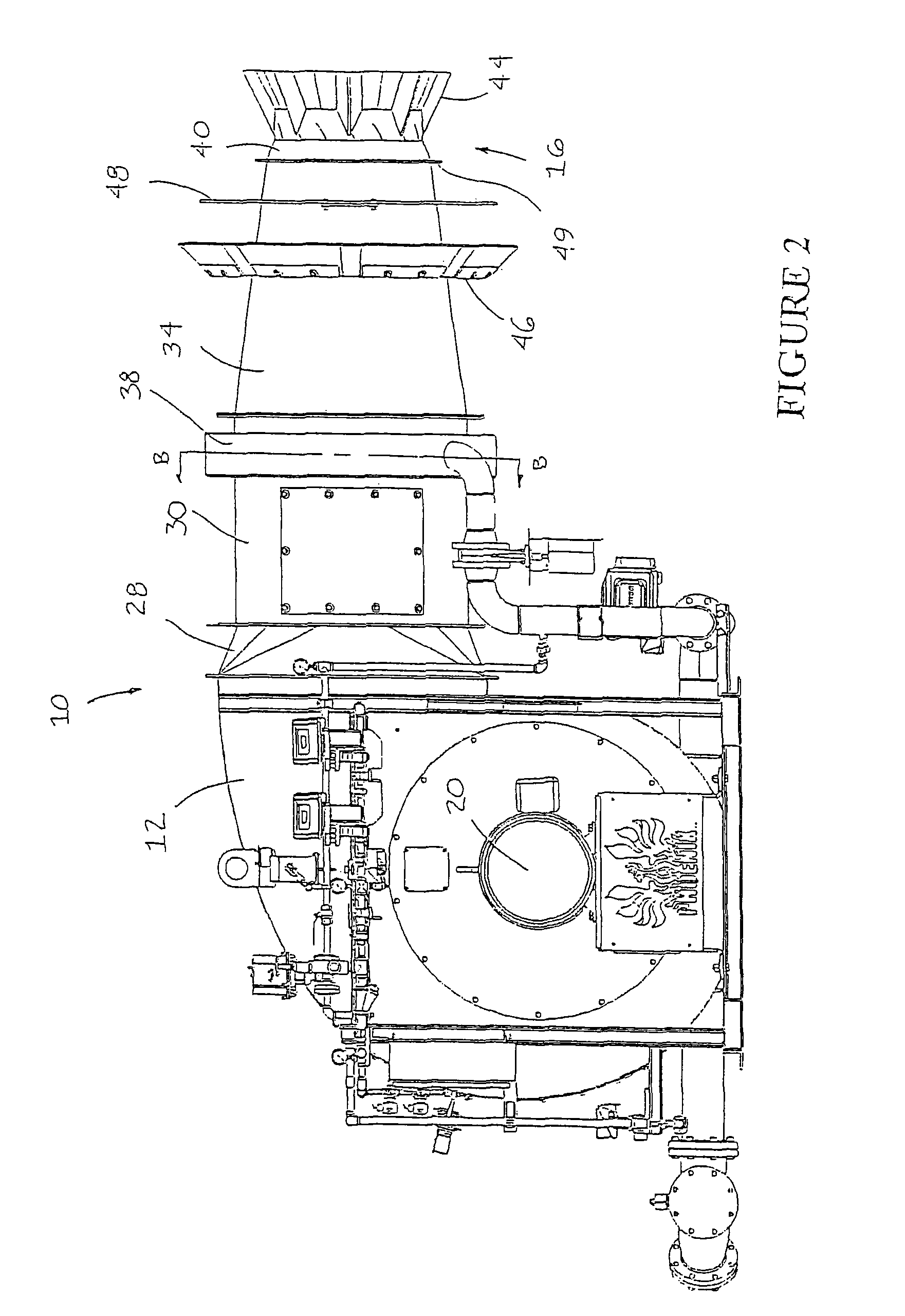
[0033]Referring now to the drawings, the apparatus of the invention described herein is illustrated by FIGS. 1 through 17. As shown in FIGS. 1 through 7, the preferred burner assembly is designated generally by reference numeral 10. The preferred burner assembly 10 is built on skid assembly SA having lifting tubes LE that allow the assembly to be handled with a fork truck or hoist. The preferred burner assembly is adapted to selectively fire on a gaseous fuel such as natural gas or a liquid fuel such as fuel oil, or both.

[0034]Referring still to FIGS. 1 through 7, the preferred burner assembly 10 comprises housing 12 having air inlet 14 (See FIGS. 3 and 6) and burner end 16 downstream from the air inlet. The preferred housing 12 generally contains the working components of the burner assembly and provides an outer shell within which combustion air may be pressurized, conveyed from the air inlet to the burner end, and mixed with fuel to produce a flame at the burner end of the housin...


PUM


Abstract

A burner assembly including a housing having an air inlet and a burner end, a motor, and an impeller mounted in the housing. The impeller is in fluid communication with the air inlet, in mechanical communication with the motor, and adapted to direct air from the air inlet towards the burner end of the housing. The burner assembly also includes at least one pre-mix gas injection nozzle mounted in the housing. Each of the at least one pre-mix gas injection nozzle has at least one orifice adapted to direct gaseous fuel into the housing. The burner assembly further includes a spin vane comprising at least one spin vane blade. The spin vane is mounted in the burner end of the housing and adapted to direct the flow of air in the burner end. The burner assembly still further includes a flattening screen located in the housing downstream from the impeller and an igniter mounted in the burner end of the housing. The igniter is adapted to ignite the air and fuel mixture in the burner end of the housing to produce a main flame.

Description

RELATED APPLICATIONS[0001]This is a continuation-in-part application of patent application entitled Burner Assembly, which was filed on Oct. 1, 2004 now abandoned and assigned Ser. No. 10 / 957,252.FIELD OF THE INVENTION[0002]This invention relates generally to an improved burner assembly, and more particularly, to an improved burner assembly for heating and drying aggregate materials used in connection with the production of hot mix asphalt.BACKGROUND AND DESCRIPTION OF THE PRIOR ART[0003]It is known to use a burner assembly to heat and dry aggregate materials used in connection with the production of hot mix asphalt. See, e.g., U.S. Pat. No. 5,700,143, U.S. Pat. No. 5,511,970, U.S. Pat. No. 4,559,009 and U.S. Pat. No. 4,298,337. However, conventional burner assemblies suffer from several disadvantages. For example, conventional burner assemblies are incapable of producing a flame configuration satisfactory for asphalt production in a variety of different-sized combustion chambers. A...

Claims


Application Information

Patent Timeline
Patent Type & Authority Patents(United States)
IPC IPC(8): F23C5/08
CPCF23D14/36F23D14/64F23D14/70F23D2900/00003F23D2900/14004F23D2900/14021
Inventor SWANSON, MALCOLMSWANSON, MICHAEL
Owner ASTEC
Why Eureka
Try Eureka