
Systems and methods for carbon dioxide capture

a carbon dioxide and carbon dioxide technology, applied in liquid degasification, separation processes, dispersed particle separation, etc., can solve the problems of significant additional capital cost, significant portion of the capital cost of the recovery system, and significant igcc system capital cos

Active Publication Date: 2011-02-22
AIR PROD & CHEM INC
View PDF18 Cites 6 Cited by
  • Summary
  • Abstract
  • Description
  • Claims
  • Application Information

AI Technical Summary

Benefits of technology

The patent text describes a method and system for removing carbon dioxide from gases produced by a power system. The system includes an acid gas stripper to remove acid gas from a rich solvent to create a CO2 stream, a compressor to pressurize the CO2 stream, and a carbon dioxide sequestration system to channel the pressurized CO2 stream to a safe location. The technical effect of this patent is to provide a more efficient and effective way to remove carbon dioxide from power system emissions.

Problems solved by technology

However, such a sulfur recovery system, including the SRU and TGU, represents a significant portion of the capital cost of an IGCC system.
Moreover, when an IGCC power plant incorporates pre-combustion CO2 separation and purification systems, a significant additional capital cost is incurred.

Method used


Image

  • Systems and methods for carbon dioxide capture
  • Systems and methods for carbon dioxide capture
  • Systems and methods for carbon dioxide capture

Examples


Embodiment Construction

[0011]As used herein, the term “lean” is used to describe a solvent that is substantially emissions free, and the term “rich” is used to describe a solvent containing emissions. Similarly, the term “emissions-heavy” is used to describe a gas that contains emissions.

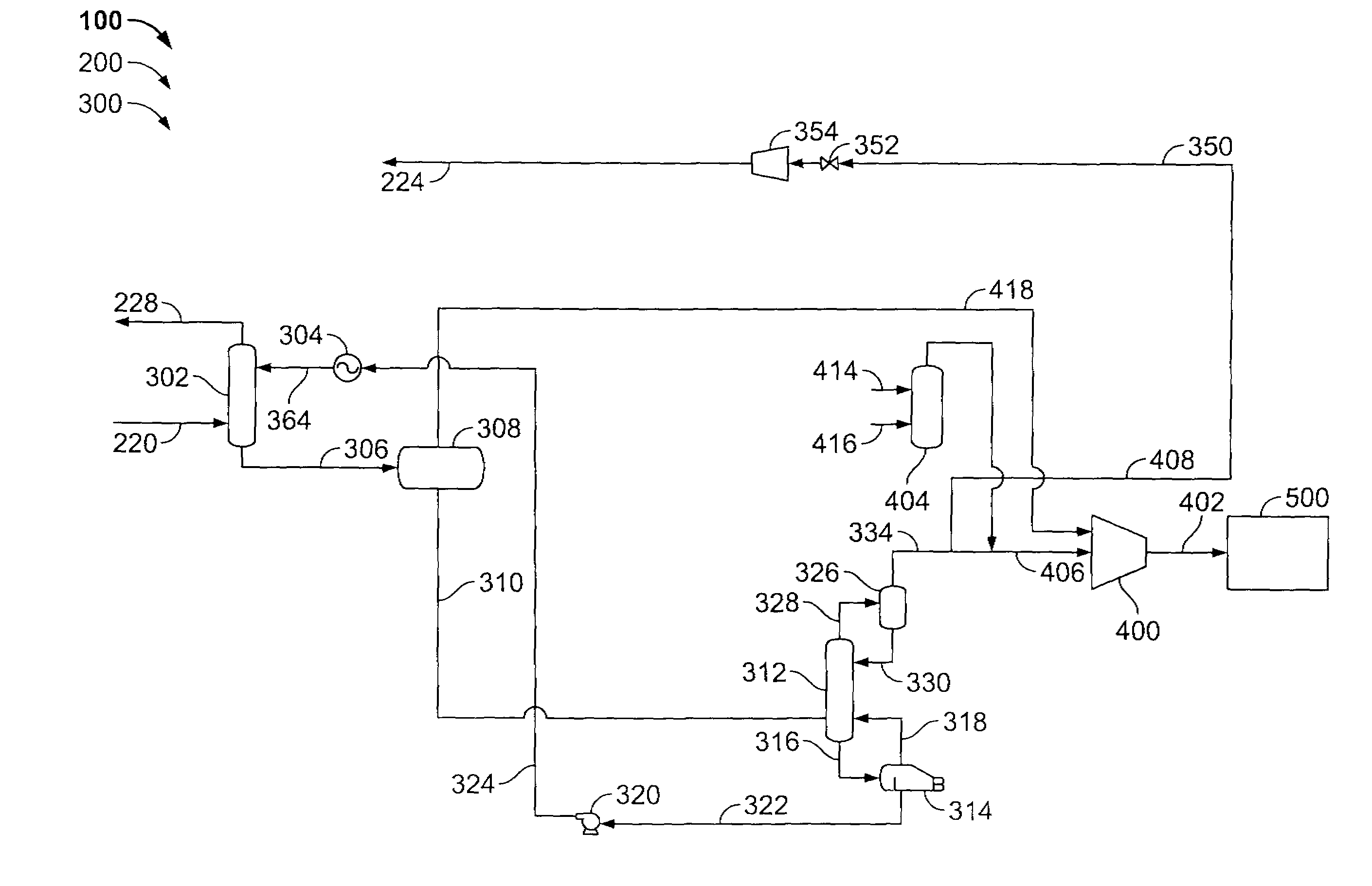
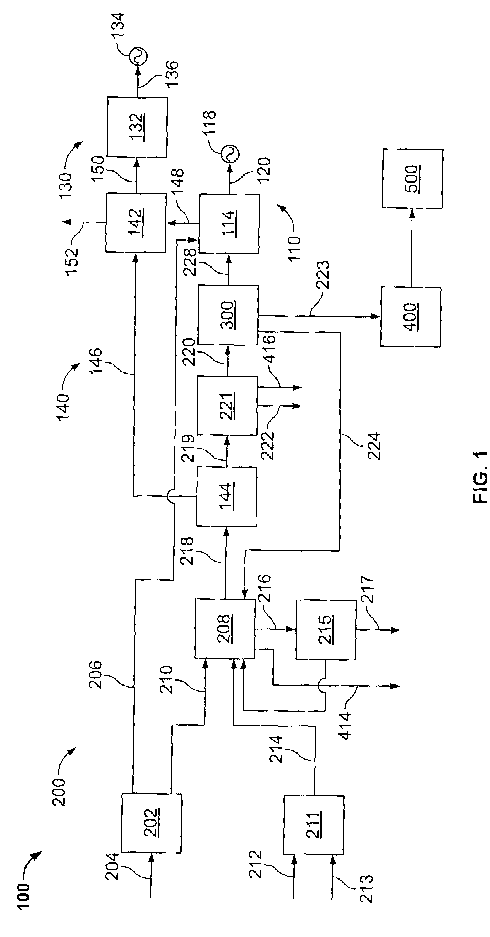
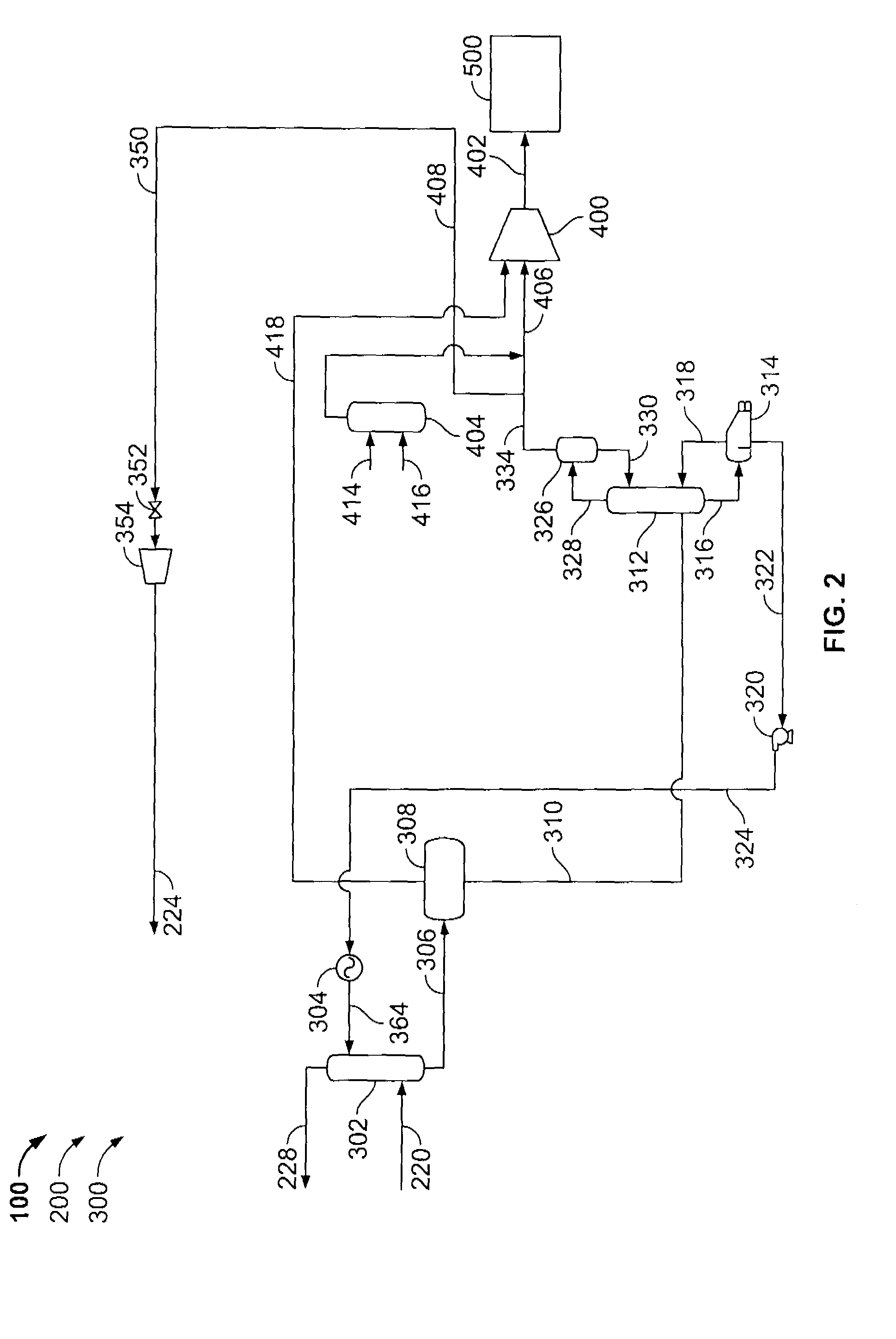
[0012]FIG. 1 is a schematic diagram of an exemplary integrated gasification combined-cycle (IGCC) power generation system 100, such as those used in power plants. In the exemplary embodiment, IGCC system includes a gas turbine engine 110. Turbine 114 is rotatably coupled to a first electrical generator 118 via a first rotor 120. Turbine 114 is coupled in flow communication with at least one fuel source and at least one air source (both described in more detail below) and is configured to receive the fuel and air from the fuel source and the air source, respectively. Turbine 114 produces rotational energy that is transmitted to generator 118 via rotor 120, wherein generator 118 converts the rotational energy to electrical ...


PUM

PropertyMeasurementUnit
temperatureaaaaaaaaaa
pressureaaaaaaaaaa
acidaaaaaaaaaa

Abstract

Methods and systems for handling sour carbon dioxide (CO2) streams are provided. In one aspect, a method for sequestering an emissions-heavy gas includes removing at least a portion of an acid gas from a rich solvent in an acid gas stripper to create the emissions-heavy gas, and channeling the emissions-heavy gas to a storage system.

Description

BACKGROUND OF THE INVENTION[0001]This invention relates generally to gasification systems and, more particularly, to systems and methods for capturing a rich carbon dioxide (CO2) stream produced by gasification systems.[0002]At least some known gasification systems, such as those used in power plants, are integrated with at least one power-producing turbine system, thereby forming an integrated gasification combined-cycle (IGCC) power generation system. For example, at least some known gasification systems convert a mixture of fuel, air or oxygen (O2), steam, and / or carbon dioxide (CO2) into a synthetic gas, or “syngas.” The syngas is channeled to the combustor of a gas turbine engine, which powers a generator that supplies electrical power to a power grid. Exhaust from at least some known gas turbine engines is supplied to a heat recovery steam generator that generates steam for driving a steam turbine. Power generated by the steam turbine also drives an electrical generator that p...

Claims


Application Information

Patent Timeline
Patent Type & Authority Patents(United States)
IPC IPC(8): B01D53/14
CPCB01D53/1462B01D53/77B01D2256/16B01D2256/20Y02C10/08B01D2257/406B01D2257/504Y02C10/06B01D2257/304Y02C20/40
Inventor FRYDMAN, ARNALDOTHACKER, PRADEEPNAPHAD, SACHINAVAGLIANO, AARON JOHN
Owner AIR PROD & CHEM INC
Learn More