

Methods and systems for reducing tensile residual stresses in compressed tubing and metal tubing products produced from same
a technology of compressed tubing and compressed tubing, which is applied in the direction of mechanical equipment, engine components, other domestic articles, etc., can solve the problems of affecting the quality of welds, and reducing the mechanical properties of the material, so as to reduce the stress state of compressed ends, reduce the loss of mechanical strength, and reduce the stress state of tensile residual stress
- Summary
- Abstract
- Description
- Claims
- Application Information
AI Technical Summary
Benefits of technology
Problems solved by technology
Method used
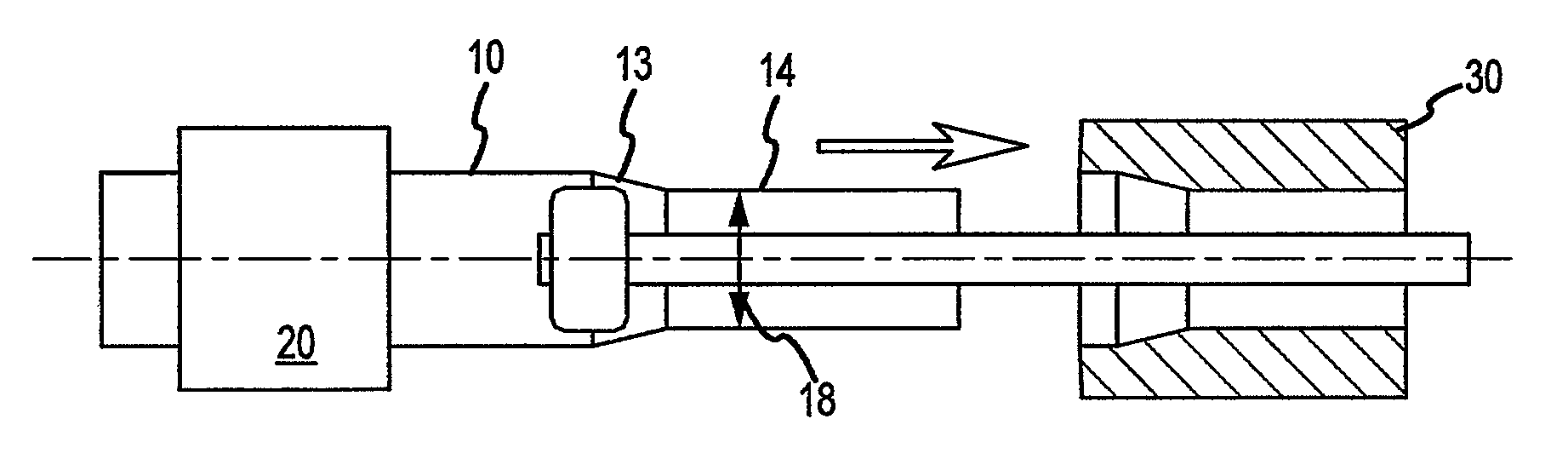
Image

Examples
example 1
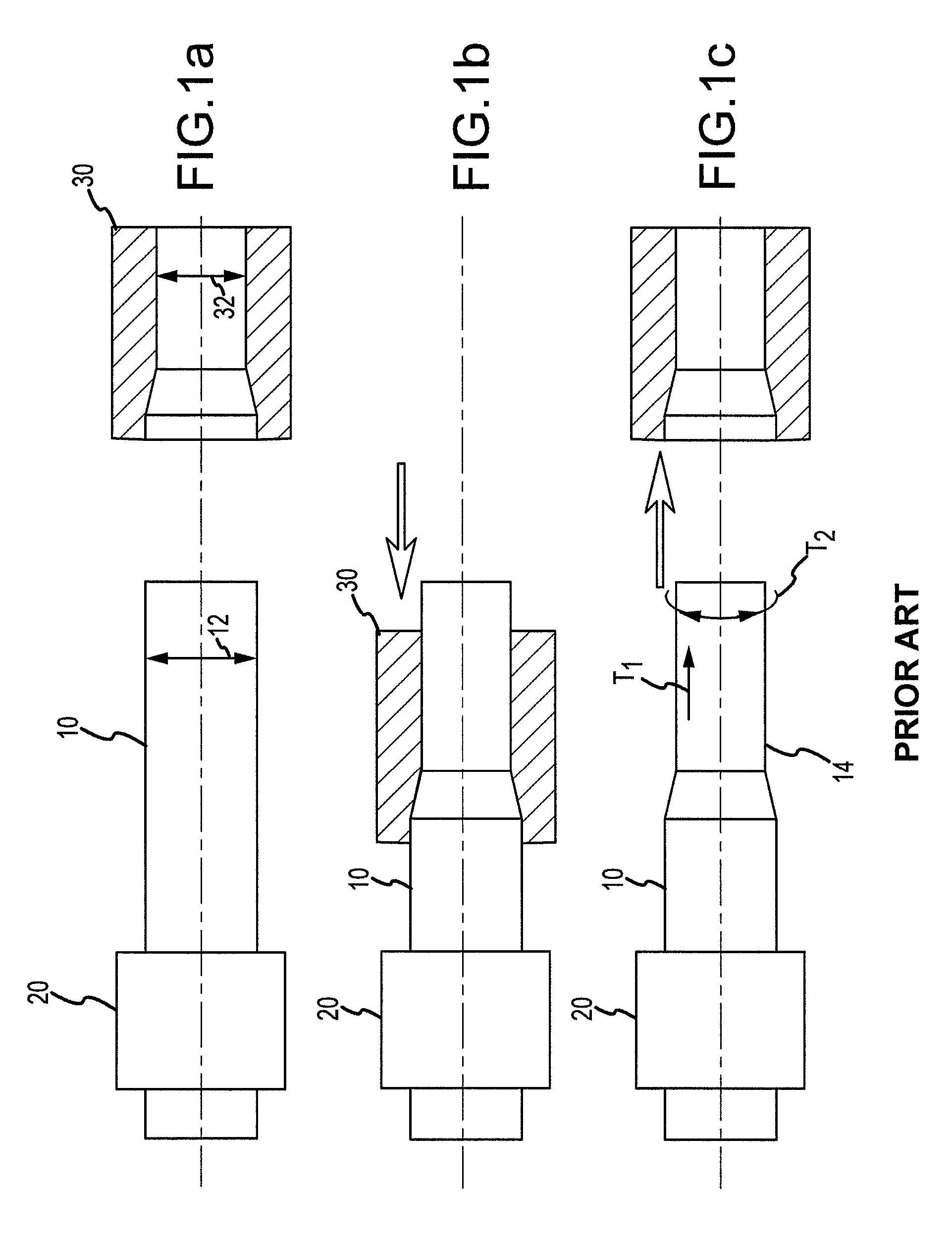
Production of Tubing End Via Conventional Process
[0044]A compressed tubing end of a 6061 series aluminum alloy is produced substantially in accordance with FIGS. 1(a)-1(c) and the description associated therewith. The residual axial hoop stress of the tubing end is measured via the Espey and Sachs method. The diameter before testing is about 4.528 inches. The diameter after testing is about 4.728 inches. The residual hoop stress is measured to be about 10.17 ksi.
example 2
Production of Tubing End Via Conventional Process with Subsequent Heat Treatment
[0045]A compressed tubing end of a 6061 series aluminum alloy is produced substantially in accordance with FIGS. 1(a)-1(c) and the description associated therewith. After production, the compressed end is heat treated via conventional processes. The residual axial hoop stress of the tubing end is measured via the Espey and Sachs method. The diameter before testing is about 4.532 inches. The diameter after testing is about 4.532 inches. The residual hoop stress is measured to be about 0 ksi.
example 3
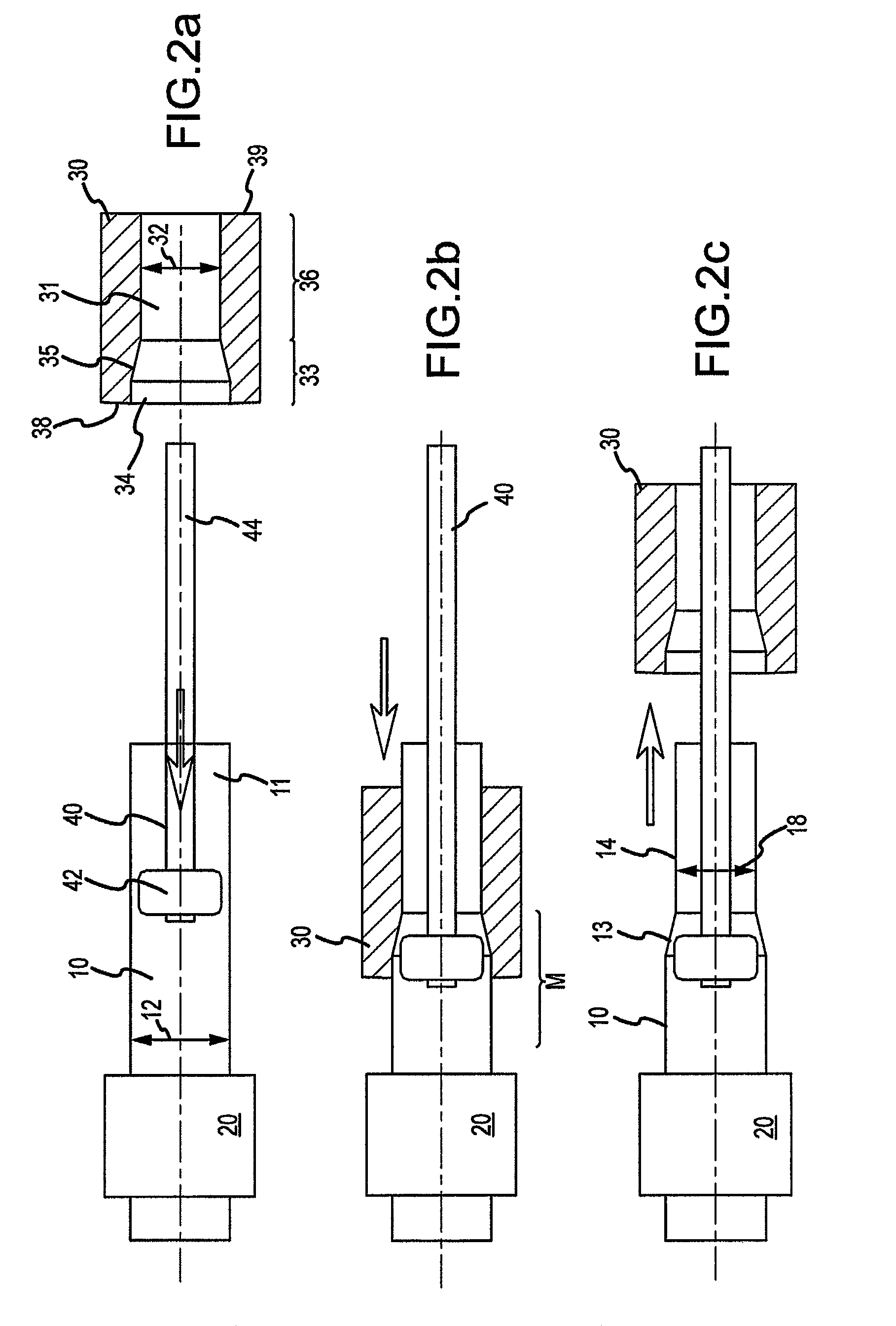
Production of Stress-Relieved Tubing End Via Expander
[0046]A compressed tubing end of a 6061 series aluminum alloy is produced substantially in accordance with FIGS. 2(a)-2(d) and the description associated therewith. After production, the residual axial hoop stress is measured via the Espey and Sachs method. The diameter before testing is about 4.525 inches. The diameter after testing is about 4.492 inches. The residual hoop stress is measured to be about −1.95 ksi.
PUM
| Property | Measurement | Unit |
|---|---|---|
| outer diameter | aaaaa | aaaaa |
| outer diameter | aaaaa | aaaaa |
| outer diameter | aaaaa | aaaaa |
Abstract
Description
Claims
Application Information