Pneumatic drive system

a technology of pneumatic drive and drive shaft, which is applied in the direction of portable percussive tools, drilling machines, couplings, etc., can solve the problems of limited air requirements and other problems, and achieve the effect of reducing the flow cross section

Inactive Publication Date: 2011-03-01
FESTO AG & CO KG
View PDF9 Cites 4 Cited by
  • Summary
  • Abstract
  • Description
  • Claims
  • Application Information

AI Technical Summary

Benefits of technology

[0019]A further advantage may be produced, if the control valve means have a third switching position, in which the compressed air goes through a flow cross section smaller than the choke's cross section. This switching setting will be termed the hold setting, because it takes effect to hold the output drive unit in its end of stroke position. The hold setting of the control valve means takes effect in a manner dependent on the position of the output drive unit, when the latter gets near or reaches the end of stroke position. Switching over may be caused mechanically, for example owing to a plunger-like setting member cooperating with the output drive unit, or however also electrically using suitable position se

Problems solved by technology

Owing to the choke cross section then effective the degree of filling of the connected work

Method used


Image

  • Pneumatic drive system
  • Pneumatic drive system

Examples


Embodiment Construction

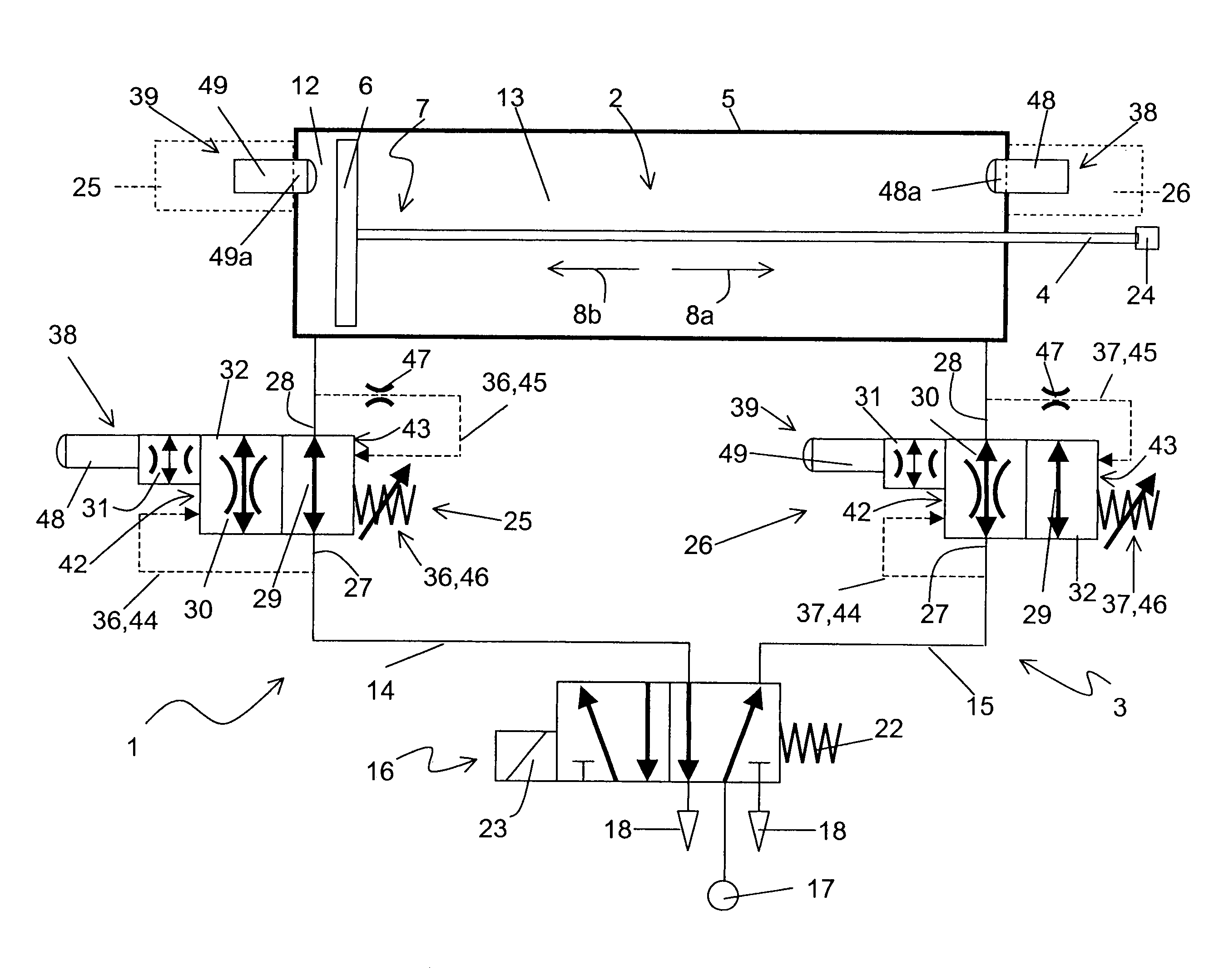
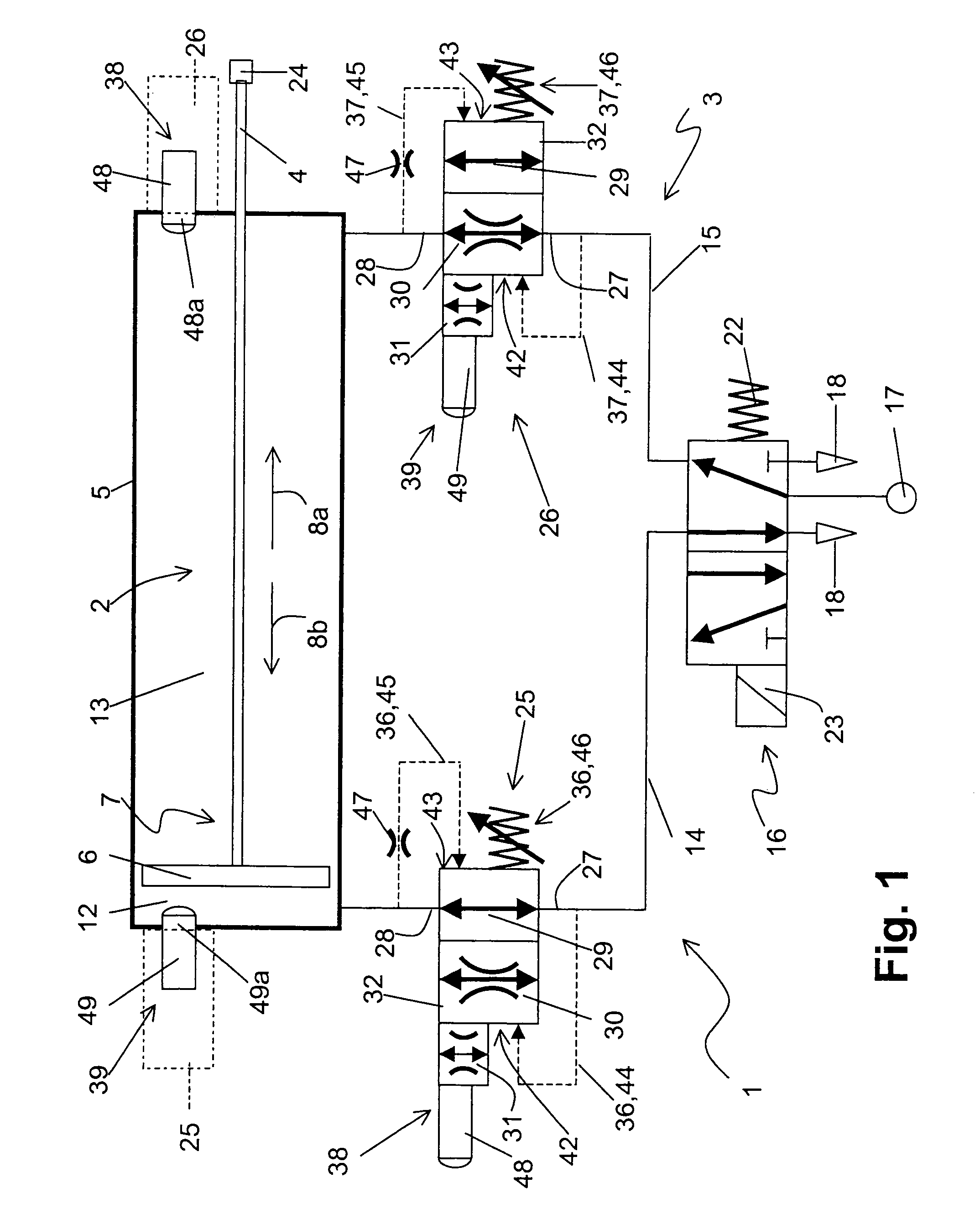
[0021]The pneumatic drive system generally referenced 1 comprises at least one pneumatic drive 2 which may conveniently be a linear drive. It is provided with a control means generally referenced 3 serving for control during operation.

[0022]The pneumatic drive 2 is in principle of any desired construction. For instance it could be in the form of a linear drive without a piston rod. For instance it can be a pneumatic cylinder having a piston rod 4.

[0023]The pneumatic drive 2 includes a housing which is termed the drive housing 5 and has a certain longitudinal extent, in whose internal space a linearly sliding drive piston 6 is located, which is combined with the above mentioned piston rod 4 to constitute a moving unit termed a output drive unit 7. This output drive unit 7 is able to be shifted longitudinally to perform either an outward or an inward working movement 8a and 8b in relation to the drive housing 2 linearly.

[0024]The internal space unit drive housing 5 is divided up by th...


PUM

PropertyMeasurementUnit
Forceaaaaaaaaaa
Pressureaaaaaaaaaa
Flow rateaaaaaaaaaa

Abstract

A pneumatic drive system (1) in which the movement of an output drive unit (7) of a pneumatic drive (2) is controlled by a control valve (25 and 26) which is connected with the working chambers (12 and 13) of the pneumatic drive (2). The control valve (25 and 26) comprises least one air economy setting (30) setting a choke cross section and a high power setting (29) defining a flow cross section larger than it. An actuator serves to ensure that the control valve is switched over, in a fashion dependent on the air pressure obtaining in the at least one working chamber (12 and 13) from the normally assumed air economy setting (30) into the high power setting (29), when the output drive unit (7) meets with an increased resistance to motion.

Description

[0001]This application claims priority based on an International Application filed under the Patent Cooperation Treaty, PCT / EP2006 / 001538, filed Feb. 21, 2006.BACKGROUND OF THE INVENTION[0002]The invention relates to a pneumatic drive system comprising at least one pneumatic drive having a drive housing and an output drive unit able to be shifted in relation to it by the action of compressed air, said output drive unit possessing an output piston, which in the drive housing divides two working chambers from each other, of which one or both is connected with control valve means serving for the controlled action of compressed air, said control valve means being able to be switched over between several switching settings which include an air economy setting defining a choke cross section.[0003]A pneumatic drive system of this type as disclosed in the patent publication WO 02 / 14698 A1 is employed for crust breaking applications in aluminum processing. The system comprises a pneumatic dr...

Claims


Application Information

Patent Timeline
IPC IPC(8): F15B11/042
CPCF15B11/042F15B2211/30525F15B2211/327F15B2211/40515F15B2211/455F15B2211/46F15B2211/50563F15B2211/6336F15B2211/7053F15B2211/775
Inventor HIRLING, ULRICHCASIMIR, UTE
Owner FESTO AG & CO KG
Why Eureka
Try Eureka