Permanent magnet type rotary machine

a permanent magnet and rotary machine technology, applied in the direction of magnet circuit shape/form/construction, instruments, horology, etc., can solve the problems of increasing cogging torque and rotational vibration, increasing causing rotational fluctuation and vibration, so as to reduce the resultant cogging torque of the whole rotary machine and reduce the cogging torque. , the effect of high reduction of cogging torqu

Inactive Publication Date: 2011-03-01
SHINANO KENSHI
View PDF32 Cites 21 Cited by
  • Summary
  • Abstract
  • Description
  • Claims
  • Application Information

AI Technical Summary

Benefits of technology

[0010]An object of the present invention is to provide a permanent magnet type rotary machine, which is small in size and capable of reducing cogging torque caused by variation of amounts of magnetic flux in magnetic circuits formed between magnetic pole teeth of adjacent stator yokes.
[0018]the supplementary magnetic pole has magnetic pole teeth arranged with a prescribed phase difference to the magnetic pole teeth of the adjacent stator yoke so as to reduce cogging torque generated by a magnetic circuit formed in boundary face between the adjacent stator yokes.
[0020]In the permanent magnet type rotary machine of the present invention, the stator units in one phase is divided into n (n is an integer one or more), and the magnetic centers of at least one pair of the magnetic pole teeth of the adjacent stator yokes, which are vertically arranged, are shifted with the prescribed phase difference so as to highly reduce their cogging torque. With this structure, the cogging torque, which is caused by variation of amounts of magnetic flux in magnetic circuits formed between the magnetic pole teeth of the adjacent stator yokes, can be offset by the phase difference, so that the resultant cogging torque of the whole rotary machine can be reduced. Especially, the cogging torque caused by variation of amounts of the magnetic flux in the magnetic circuits, which are formed between the magnetic pole teeth of the vertically stacked stator yokes by passing the magnetic flux therethrough, can be effectively reduced. In case that the magnetic centers of at least one pair of the magnetic pole teeth of the adjacent stator yokes, which are vertically arranged, are shifted with the phase difference of 90°+−30°, preferably 90°, the cogging torque can be highly reduced.
[0021]By using a rare-earth magnet, whose maximum energy product is high, and increasing number of the stacked stator units, a total sectional area of the stator yokes can be broadened so that the small permanent magnet type rotary machine, which is capable of generating large torque, can be produced without considerably increasing processing accuracy and production costs.
[0022]In case that the supplementary magnetic pole is coaxially stacked on an even number of the stator units and has the magnetic pole teeth arranged with the prescribed phase difference for highly reducing the cogging torque generated by the magnetic circuit formed in the boundary face between the adjacent stator yokes, said cogging torque can be highly reduced.
[0023]By forming the space between the adjacent stator units vertically stacked, magnetic circuits passing through the magnetic pole teeth of the vertically adjacent stator units are magnetically blocked, so that the cogging torque, which is caused by variation of amounts of magnetic flux in the magnetic circuits, can be reduced.

Problems solved by technology

Cogging torque elements become high harmonic elements of motor torque, so rotational fluctuation and vibration are caused.
Therefore, cogging torque and rotational vibration are increased, and rotational fluctuation become worse.
However, in the permanent magnet type rotary machine having comb-shaped magnetic pole teeth, it is difficult to precisely form the stator yokes by press working.
Further, a die set for the pressing work must be large, so that a huge manufacturing facility must be required and the production cost must be increased.

Method used


Image

  • Permanent magnet type rotary machine
  • Permanent magnet type rotary machine
  • Permanent magnet type rotary machine

Examples


Embodiment Construction

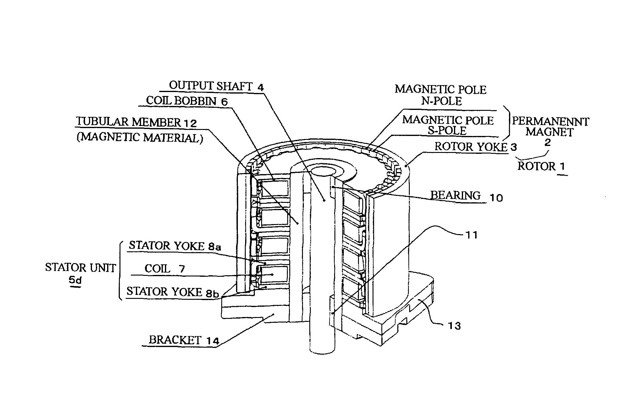
[0044]Preferred embodiments of the present invention will now be described in detail with reference to the accompanying drawings. In the following embodiments, step motors will be explained as the permanent magnet type rotary machines.

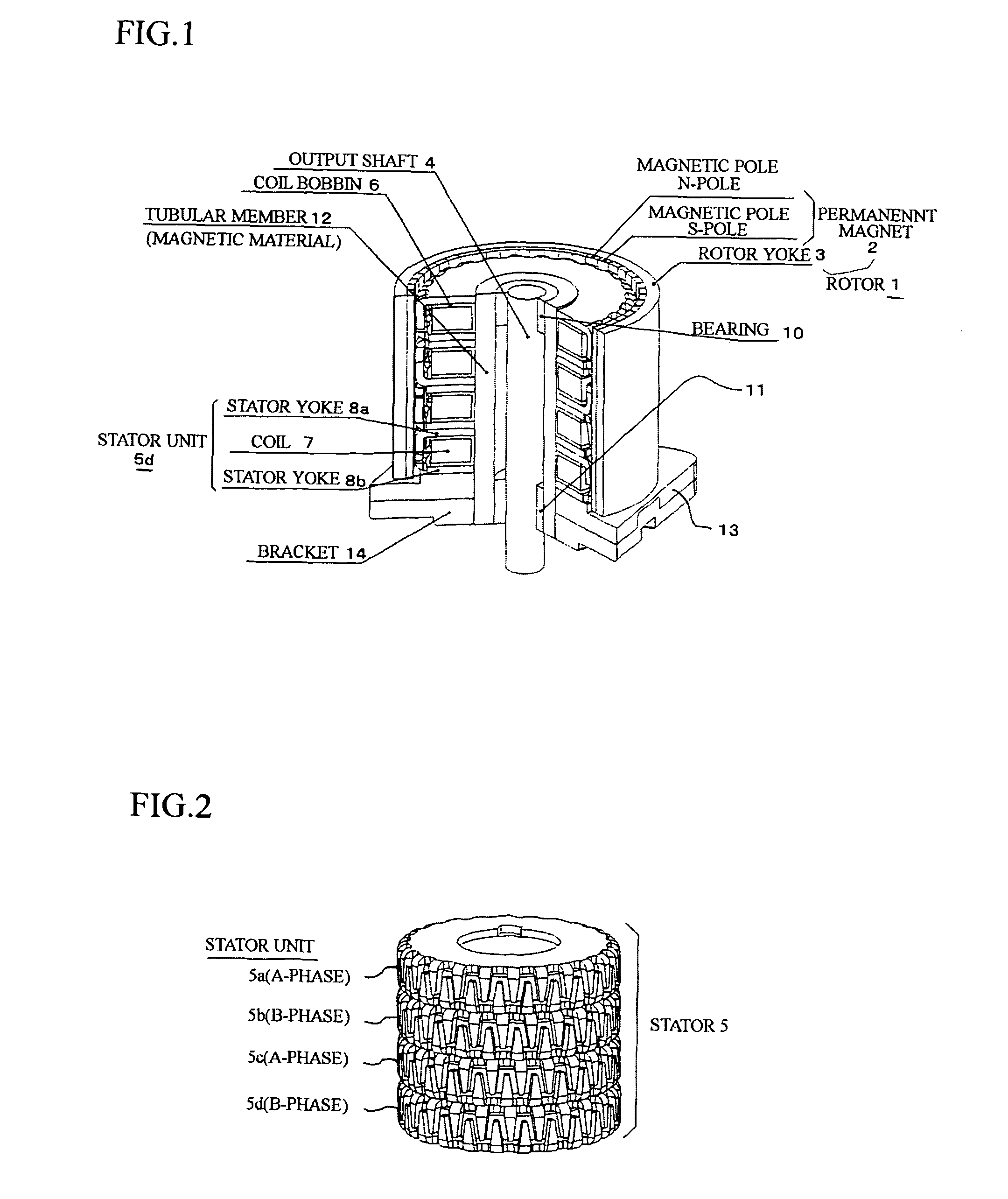
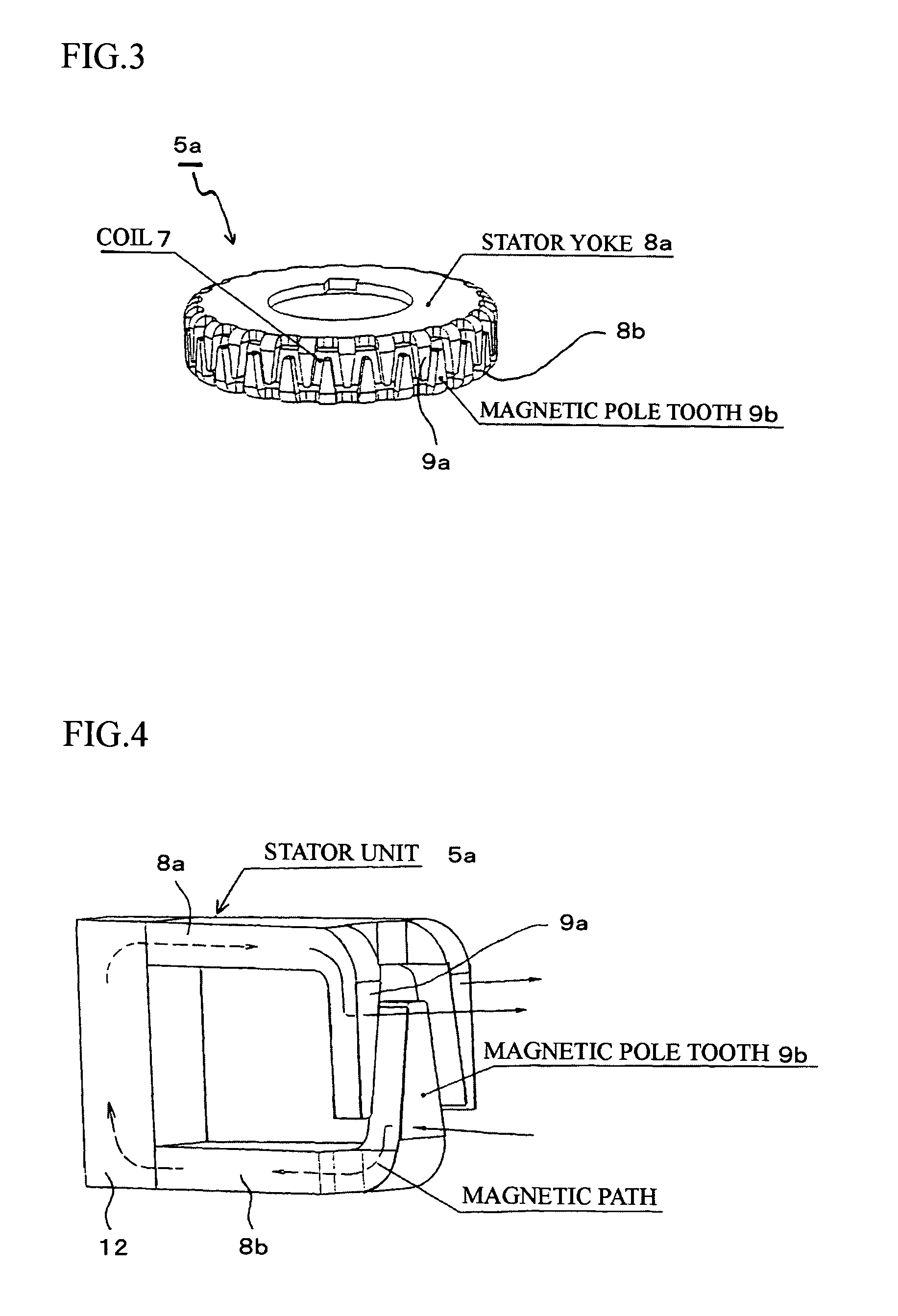
[0045]In each of the embodiments, the step motor is a claw pole type step motor comprising: a stator constituted by a plurality of stator units, which are coaxially stacked and in each of which a coil is sandwiched between stator yokes and magnetic pole teeth (claw poles) are mutually engaged; and a rotor including a permanent magnet having magnetic poles, which respectively face the claw poles of the stator yokes.

[0046]An example for the explanation is given as the step motor, which is an outer rotor type two-phase step motor, and is assembled in office automation machines, peripheral equipment of a computer system, vehicles, factory automation machines, e.g., conveyor, etc.

[0047]An outline of the two-phase step motor will be explained with reference ...


PUM


Abstract

The permanent magnet type rotary machine is capable of reducing cogging torque caused by variation of amounts of magnetic flux in magnetic circuits. The permanent magnet type rotary machine comprises: a stator constituted by stator units, which are coaxially stacked and in each of which a coil is sandwiched between stator yokes; and a rotor including a permanent magnet having magnetic poles, which respectively face magnetic pole teeth of the stator yokes, the rotor being rotatably supported by an output shaft. The stator units in one phase is divided into n (n is an integer one or more), and magnetic centers of at least one pair of the magnetic pole teeth of the adjacent stator yokes, which are vertically arranged, are shifted with a prescribed phase difference so as to mutually cancel their cogging torque.

Description

BACKGROUND OF THE INVENTION[0001]The present invention relates to a permanent magnet type rotary machine employed in office automation machines, e.g., copier, printer, peripheral equipments of a computer system, vehicles, factory automation machines, e.g., conveyor, etc.[0002]There are many permanent magnet type rotary machines—such as a PM type step motor having a permanent magnet rotor, a hybrid (HB) type step motor having a gear-shaped iron core and a permanent magnet, and a brushless motor having a magnetic pole detecting unit for feedback control. A permanent magnet type rotary machine, which has comb-shaped magnetic pole teeth facing a rotor, includes: a plurality of stator units stacked in the axial direction; and a rotor having a permanent magnet, which faces the stator units and is alternately magnetized as N-poles and S-poles. By passing a current through coils of the stator units with switching the current direction, stator magnetic poles and rotor magnetic poles mutually...

Claims


Application Information

Patent Timeline
Patent Type & Authority Patents(United States)
IPC IPC(8): H02K37/00H02K37/12H02K37/14
CPCH02K1/145H02K37/14
Inventor USUI, HIROAKI
Owner SHINANO KENSHI
Why Eureka
Try Eureka