
Enhancement of conventional SCR and SNCR processes with ammonia destruction catalyst

a technology of destruction catalyst and ammonia, which is applied in the direction of emission prevention, separation process, and flue gas purification components, can solve the problems of precious metal catalysts being less attractive, ammonia levels, and their potential to oxidize, so as to increase the efficiency and flexibility of control, increase the efficiency and flexibility, and increase the effect of nox removal

Inactive Publication Date: 2011-03-08
THE BABCOCK & WILCOX CO
View PDF19 Cites 1 Cited by
  • Summary
  • Abstract
  • Description
  • Claims
  • Application Information

AI Technical Summary

Benefits of technology

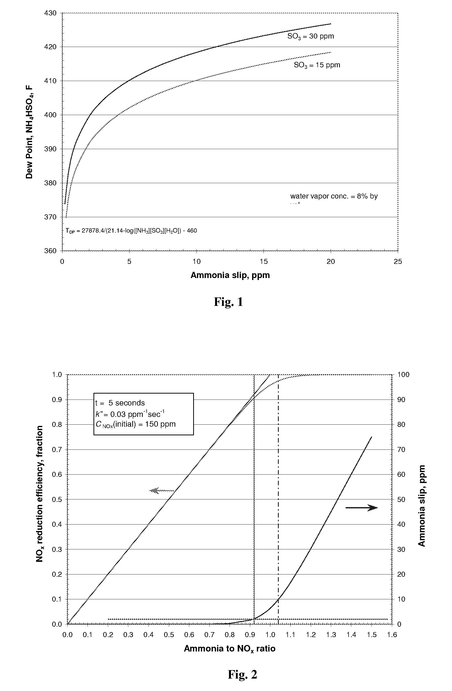
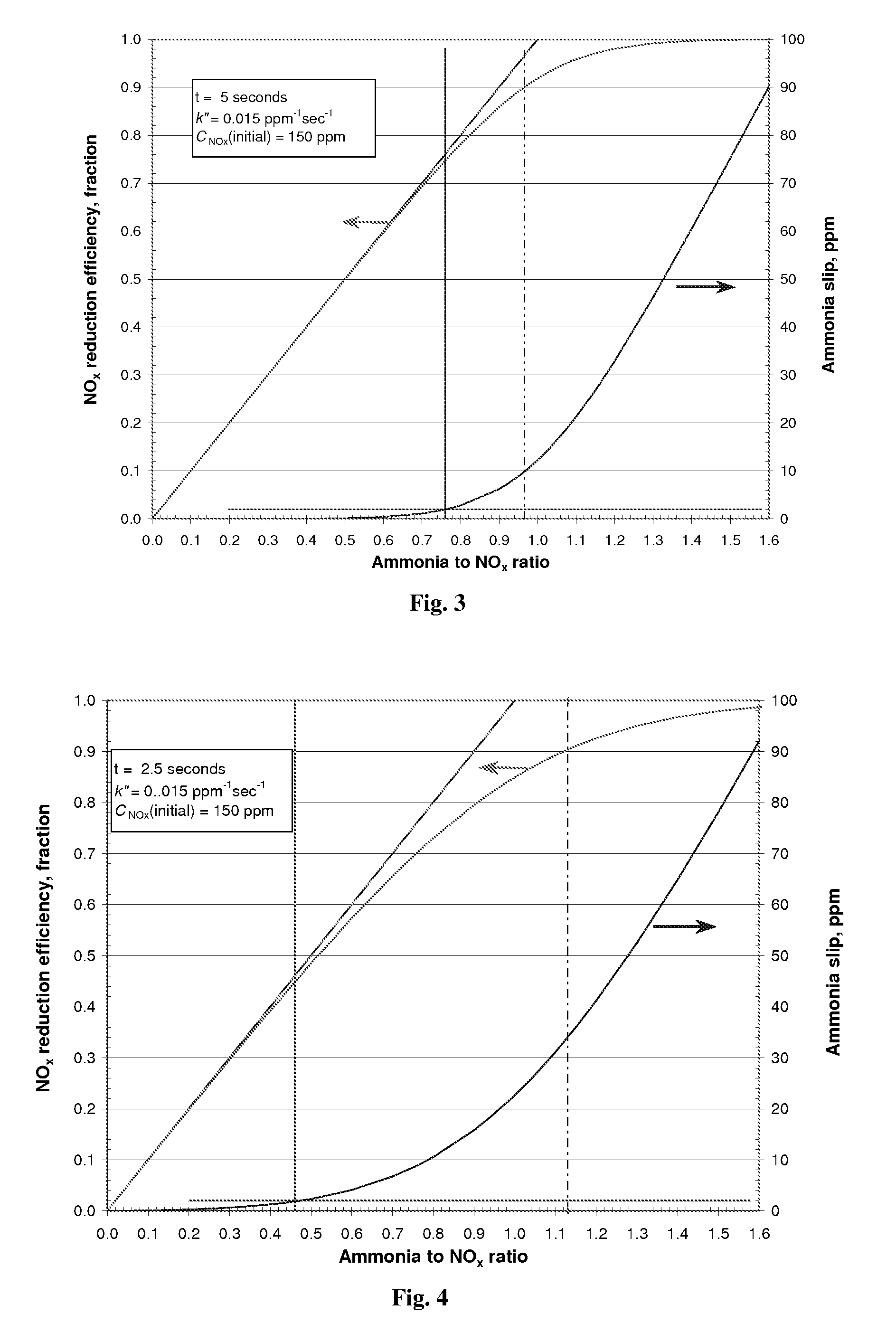
1. For existing SCR installations where the catalyst activity has begun to degrade, the present invention allows the plant operator to increase the ammonia supply rate and achieve increased NOx removal, without increasing ammonia slip. NOx performance can be maintained at required levels resulting in less downtime and longer-lived catalyst by simply increasing the ammonia flow rate.
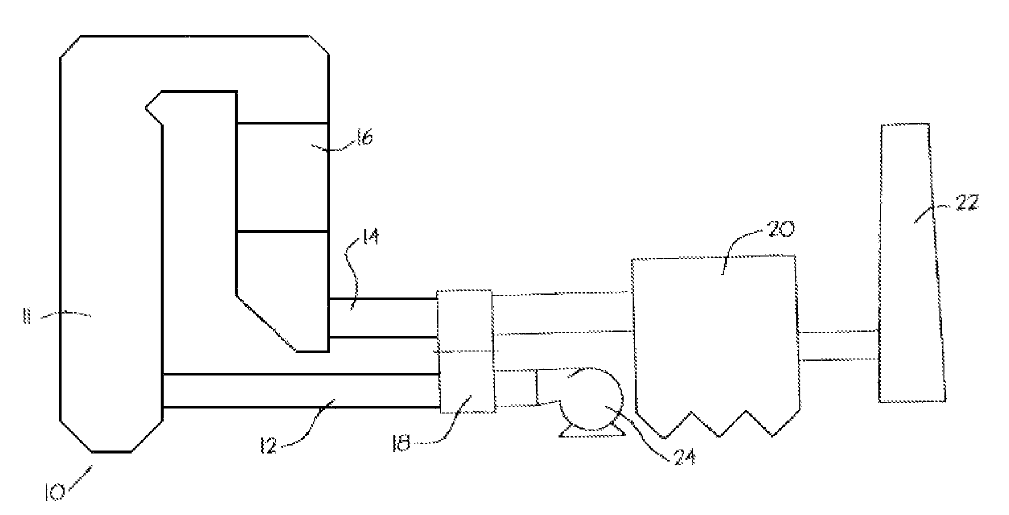
In still another aspect of the present invention, there is provided a method for achieving increased NOx removal efficiency in an emissions control system for a boiler while controlling ammonia slip, the method comprising the steps of: providing a flue for conveying flue gases from the boiler to a stack for discharge; positioning a NOx reduction system comprising at least one selective catalytic reduction system along the flue between the boiler and the stack, the NOx reduction system being constructed so as the remove at least NOx from the flue gas conveyed along the flue, wherein the NOx reduction system relies in whole, or in part, upon ammonia introduced into the NOx reduction system via at least one ammoniacal compound injection point; determining a desired NOx removal efficiency for the at least one selective catalytic reduction system and providing an excess stoichiometric ratio of ammonia to NOx to achieve the desired NOx removal efficiency regardless of the amount of ammonia slip from the NOx removal system that would otherwise be produced; and positioning an ammonia reduction system downstream of the one or more selective catalytic reduction systems, wherein the ammonia reduction system contains at least one ammonia destruction catalyst and the ammonia destruction catalyst permits the one or more selective catalytic reduction systems to be operated at the excess stoichiometric ratio of ammonia to NOx to achieve increased NOx removal efficiency without a corresponding increase in ammonia slip downstream of the ammonia reduction system.

Problems solved by technology

Rather, it is a practical limit set to prevent excessive levels of ammonia slip.
The major drawback of the base metal catalyst is its potential to oxidize SO2 to SO3; the degree of oxidation varies based on catalyst chemical formulation.
However, SO2 oxidation to SO3 and high material costs often make precious metal catalysts less attractive.
The problem with ammonia slip is that it is increasingly unacceptable to the utility customer.
It can even affect the salability of the fly ash for use in cement.
For coal fired boilers the principal problem arises from the reaction of ammonia with SO3 to form ammonium bisulfate.
This acidic sticky substance will accumulate fly ash and produce deposits that are difficult to remove.
However, with increasing ammonia slip various undesirable compounds will be generated potentially causing problems in downstream equipment and / or increased stack opacity.
Another problem associated with ammonia slip involves the particulate control device (e.g., an electrostatic precipitator).
For example, problems have been observed with ammonia evolving from fly ash collected in the hoppers of the particulate collection device and subsequently used as fillers in cement.
However, if these ashes accumulate ammonia under acid conditions, they could easily reverse the reaction when exposed to the alkaline conditions in cement.
The final fate of ammonia is perhaps the most problematic of all.

Method used


Image

  • Enhancement of conventional SCR and SNCR processes with ammonia destruction catalyst
  • Enhancement of conventional SCR and SNCR processes with ammonia destruction catalyst
  • Enhancement of conventional SCR and SNCR processes with ammonia destruction catalyst

Examples


Embodiment Construction

While the present invention will be described in terms of SCR and / or SNCR systems which use ammonia as the NOx reducing agent, since ammonia is frequently preferred for economic reasons, the present invention is not limited to ammonia based systems. The concepts of the present invention can be used in any system which uses an ammoniacal compound. As used in the present disclosure, an ammoniacal compound is a term meant to include compounds such as urea, ammonium sulfate, cyanuric acid, and organic amines as well as ammonia (NH3). These compounds could be used as reducing agents in addition to ammonia, but as mentioned above, ammonia is frequently preferred for economic reasons. Some non-ammoniacal compounds such as carbon monoxide or methane can be used as well, but with loss in effectiveness.

Although the present invention is described in relation to a boiler, or a fossil fuel boiler, it is not limited solely thereto. Instead, the present invention can be applied to any combustion s...


PUM

PropertyMeasurementUnit
temperatureaaaaaaaaaa
operating temperaturesaaaaaaaaaa

Abstract

An apparatus and method for achieving increased NOx removal efficiency from an emissions control portion of a fossil fuel fired boiler while controlling ammonia slip provides excess levels of ammonia above those levels conventionally employed in SCR and / or SNCR applications. The apparatus and methods comprise, in part, use of a NOx reduction system comprising at least one selective catalytic reduction system which receives ammonia in higher amounts than conventional practice from an upstream ammonia injection point, and an ammonia reduction system positioned downstream of one or more ammonia injection points and the NOx reduction system. The excess ammonia achieves increased NOx removal, while the ammonia reduction system contains at least one ammonia destruction catalyst which permits the NOx reduction system to be operated at an increased NOx removal efficiency without a corresponding increase in ammonia slip.

Description

FIELD AND BACKGROUND OF THE INVENTION1. Field of the InventionThe present invention relates generally to the field of emission control equipment for boilers, heaters, kilns, or other flue gas-, or combustion gas-, generating devices (e.g., those located at power plants, processing plants, etc.) and, in particular to a new and useful method and apparatus having an increased efficiency in the ability to control the emission of NOx without a simultaneous increase in the amount of ammonia slip.2. Description of the Related ArtNOx refers to the cumulative emissions of nitric oxide (NO), nitrogen dioxide (NO2) and trace quantities of other nitrogen oxide species generated during combustion. Combustion of any fossil fuel generates some level of NOx due to high temperatures and the availability of oxygen and nitrogen from both the air and fuel. NOx emissions may be controlled using low NOx combustion technology and post-combustion techniques. One such post-combustion technique is selective ...

Claims


Application Information

Patent Timeline
Patent Type & Authority Patents(United States)
IPC IPC(8): B01D53/56B01D53/58
CPCB01D53/8625B01D53/8634F22B37/008F23J15/02B01D2251/2062B01D2257/406Y02C20/10F23J2215/101F23J2217/50F23J2219/10F23J2219/20
Inventor DOWNS, WILLIAMHINER, LARRY A.GUO, XIAOYU
Owner THE BABCOCK & WILCOX CO
Learn More