
Pattern-formed substrate, color filter and liquid crystal display employing the color filter

a technology of color filter and substrate, applied in the direction of instruments, diodes, optics, etc., can solve the problems of pixel shape including partition, stripe pattern is not so high in light blockability, and color shading in each opening is affected, so as to achieve low color shading and improve pixel quality

Inactive Publication Date: 2011-03-15
TOPPAN PRINTING CO LTD
View PDF5 Cites 2 Cited by
  • Summary
  • Abstract
  • Description
  • Claims
  • Application Information

AI Technical Summary

Benefits of technology

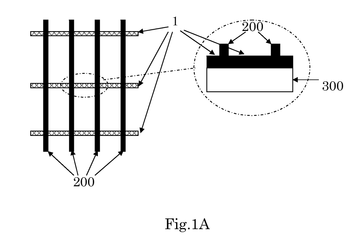
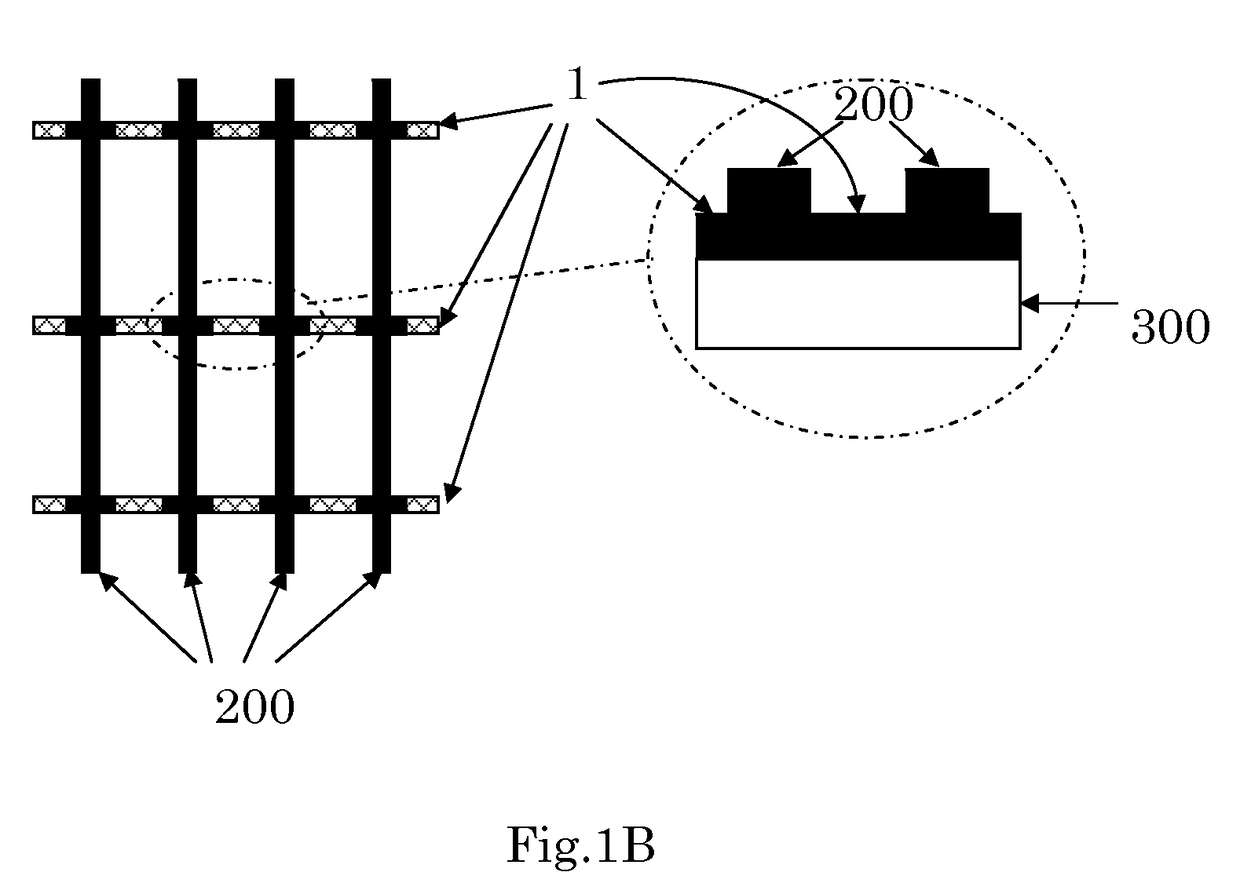
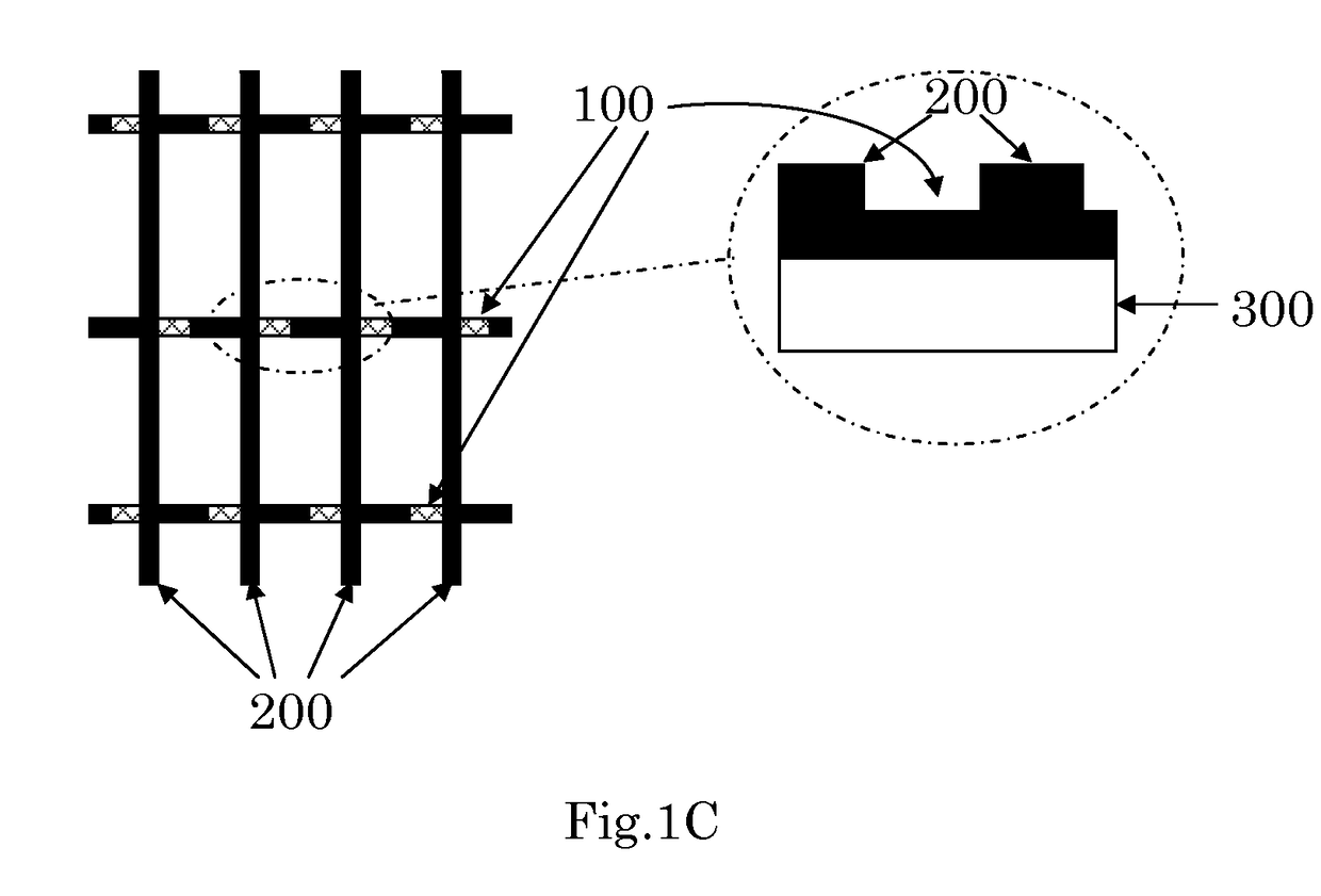
The present invention provides a pattern formation substrate with a partition pattern that can restrain variations in the amount of ink in each opening, even if the ink feed rate varies. This is achieved by making the X-direction partition pattern smaller in film thickness than the Y-direction partition pattern, and by including an area in the X-direction partition pattern where the film thickness is the same as the Y-direction partition pattern. This pattern formation substrate can produce a color filter with no color shading and uniform chromaticity. Additionally, the invention provides a pattern formation substrate with a partition pattern that can alleviate the problem of pixel shape caused by the bias of ink during the drying process.

Problems solved by technology

However, in the case where ink is filled by an inkjet method into an opening of the partition pattern formed in the grid shape, a nozzle in charge is determined for each opening, so that the problem is that variations in chromaticity of a coloring pattern in each opening are caused by variations in discharge amount in each nozzle.
On the other hand, the problem is that the stripe pattern is not so high in light blockability and inferior to the grid pattern in terms of contrast.
However, according to Patent Document 3, the pixel shape including the partition is restricted; for example, when the partition and the recess are formed in the grid shape to form a coloring pattern by an inkjet method, a possibility is brought that different inks are so adjacent as to cause color mixture.

Method used


Image

  • Pattern-formed substrate, color filter and liquid crystal display employing the color filter
  • Pattern-formed substrate, color filter and liquid crystal display employing the color filter
  • Pattern-formed substrate, color filter and liquid crystal display employing the color filter

Examples


example 1

[0103]Example 1 of the present invention is specifically described hereinafter.

[0104]Alkali-free glass was used as a transparent substrate. A photosensitive resin composition (formed by acrylic resin, cyclohexanone, carbon pigment, dispersant, compound having radical polymerizability, that is, trimethylolpropane triacrylate, and photopolymerization initiator) was applied on the transparent substrate by a spin coat method so as to have a thickness of 1.0 μm, the solvent was dried by a hot plate, exposed through a photomask produced so as to form a partition pattern in a grid shape, developed by alkali aqueous solution, and heated and fired by an oven to obtain a black matrix partition pattern in a grid shape. Next, a photosensitive resin composition containing an ink-repellent material (formed by acrylic resin, cyclohexanone, carbon pigment, dispersant, compound having radical polymerizability, that is, trimethylolpropane triacrylate, photopolymerization initiator, and fluorine-conta...

example 2

[0106]Example 2 of the present invention is specifically described hereinafter.

[0107]Alkali-free glass was used as a transparent substrate. A photosensitive resin composition containing an ink-repellent material (formed by acrylic resin, cyclohexanone, carbon pigment, dispersant, compound having radical polymerizability, that is, trimethylolpropane triacrylate, photopolymerization initiator, and fluorine-containing compound) was applied on the transparent substrate by a spin coat method so as to have a thickness of 2.0 μm, the solvent was dried by a hot plate, exposed through a photomask produced so as to form a partition pattern in a grid shape, developed by alkali aqueous solution, and heated and fired by an oven to obtain a black matrix partition pattern in a grid shape. Next, the X-direction partition pattern portion of this substrate was irradiated with a femtosecond laser and removed so that the average film thickness became 1.5 μm to form a partition pattern shown in FIG. 1B ...

example 3

[0109]Example 3 of the present invention is specifically described hereinafter.

[0110]Alkali-free glass was used as a transparent substrate. A photosensitive resin composition (formed by acrylic resin, cyclohexanone, carbon pigment, dispersant, compound having radical polymerizability, that is, trimethylolpropane triacrylate, and photopolymerization initiator) was applied on the transparent substrate by a spin coat method so as to have a thickness of 1.0 μm, the solvent was dried by a hot plate, exposed through a photomask produced so as to form a partition pattern in a grid shape, developed by alkali aqueous solution, and heated and fired by an oven to obtain a black matrix partition pattern in a grid shape. Next, a photosensitive resin composition containing an ink-repellent material (formed by acrylic resin, cyclohexanone, carbon pigment, dispersant, compound having radical polymerizability, that is, trimethylolpropane triacrylate, photopolymerization initiator, and fluorine-conta...


PUM

PropertyMeasurementUnit
optical densityaaaaaaaaaa
widthaaaaaaaaaa
widthaaaaaaaaaa

Abstract

The present invention provides a pattern formation substrate provided with a transparent substrate, a partition pattern formed on the transparent substrate in an approximately orthogonal grid shape, and a coloring pattern of plural colors, provided in an opening partitioned off with the partition pattern. The coloring pattern is formed in an approximately stripe shape in each of the colors, the partition pattern is composed of an X-direction partition pattern provided in an approximately orthogonal direction to a longitudinal direction of the stripe of the coloring pattern and a Y-direction partition pattern provided in an approximately parallel direction to the longitudinal direction of the stripe of the coloring pattern, and an average film thickness of the X-direction partition pattern is smaller than that of the Y-direction partition pattern.

Description

TECHNICAL FIELD[0001]The present invention relates to a pattern formation substrate used for a color display device, a color filter using this pattern formation substrate and a liquid crystal display device provided therewith. In particular, the present invention relates to a pattern formation substrate and a color filter which are produced by filling colored ink into an opening partitioned off with a partition pattern formed on the substrate, and a liquid crystal display device using the same.[0002]The present application claims the benefit of priority from the prior Japanese Patent Application No. 2007-232495, filed on Sep. 7, 2007, the entire contents of which are incorporated herein by reference.BACKGROUND ART[0003]In recent years, an inkjet printing system has been proposed as a method for producing a color filter used for a color display device such as a color liquid crystal display (for example, refer to Patent Documents 1 and 2).[0004]For example, it is disclosed in these pr...

Claims


Application Information

Patent Timeline
Patent Type & Authority Patents(United States)
IPC IPC(8): G02F1/1335G02F1/1333
CPCG02F1/133514G02B5/201G02B2207/121H01L27/322G02F1/133516H10K59/38
Inventor MAEDA, TADATOSHIKAMINAGA, JUNICHIKAI, TERUHIKOOHAMA, NAGANORIOZAWA, MADOKA
Owner TOPPAN PRINTING CO LTD
Learn More