Integrated sensing module for handheld spectral measurements

a sensing module and handheld technology, applied in the direction of optical radiation measurement, instruments, spectrometry/spectrophotometry/monochromators, etc., can solve the problems of limited access, limited number of instruments available for laboratory personnel, and the cost of most laboratory instruments is relatively high, so as to reduce reduce the cost. , the effect of reducing the size of the total packag

Inactive Publication Date: 2011-03-15
APPELL GEORGE N +1
View PDF112 Cites 47 Cited by
  • Summary
  • Abstract
  • Description
  • Claims
  • Application Information

AI Technical Summary

Benefits of technology

[0008]The present invention uses a miniaturized, low cost spectral sensing device, a major advancement in measurement opportunity over the status quo, and overcomes issues related to size or space occupied in the laboratory, or the size of a portable spectrometer. Each device is intended to provide the functionality of a normal spectrometer or spectral analyzer, but at reduced cost, and with a significantly reduced size for the total package.
[0013]In its standard form the fluid is drawn into the measurement region of the sensing device, as noted, via an integrated pump or suction device. The measurement region is a removable component, defined as a sampler, and is implemented in the form of a modified pipette-like structure, where the fluid is drawn in through a tip. The sampler measurement chamber includes reflective elements encapsulated and / or retained within the construction. These reflective elements capture the light / energy emerging from the source mounted within the optical interface of the spectral engine. This light / energy is then returned, in a retro-reflective manner back to the spectral sensing element (detector), which is also mounted within the optical interface of the spectral engine. In this mode of operation, the light / energy passes through the fluid at least three times; twice to and from the spectral engine and once between the two reflective elements. This produces a composite dimension, which is known as the pathlength. This is equivalent to a single pass through a conventional liquid cell. These dimensions can be set to be equivalent to normal pathlengths used in conventional cells, and these will be nominally from 1.0 mm to 10.0 cm (total distance). It is expected that in the standard format, this measurement chamber will be constructed from an optically transparent medium, and for most applications, this will be a clear plastic material. The latter is to be constructed as a molded part in the most common implementation of the device. The total sampler construction can be produced in two or more parts, with the inner measurement area being encased within a black and / or optically opaque external shell. In the common implementation this can be made as a co-extruded part, or as an assembly made from two or more separate molded parts. Note that the optically opaque exterior of the sampler will make a positive light seal with the outer casing of the main measurement system. In this manner, the measurement area is shielded from external light sources, thereby ensuring accurate photometry, and also enabling low-light measurements, such as fluorescence and luminescence.
[0014]In the standard mode of operation it is assumed that the fluid being measured will already contain an active chromophore (light absorbing entity related to the analyte) or fluorophore (light emitting entity related to the analyte). This chromophore / fluorophore will either be native to the material being measured or induced by the use of one or more specific reagents. The mixing of reagents to form a measurable solution is a standard practice in most testing laboratories, and it is also a standard procedure for most field-based testing. The micro-spectral sensing system described in this package has the advantage that the swept volume required for the fluid by the measurement system is in the region of a few hundred microliters to a few milliliters. This reduces significantly the overhead for reagents, and it also reduces the environmental impact for disposal of the fluid after analysis. This provides an additional advantage insofar as it makes some measurements practical that would be otherwise too expensive to perform because of the high intrinsic cost of the reagent. Examples of such measurements exist in the biotechnology and medical testing areas.
[0015]In an attempt to make the interaction of reagents with the fluid under study more efficient, in terms of ease-of-use, removing the need for mixing vessels, reducing exposure to reagents, and significant cost reductions for expensive reagents, Smart Tips™ or Smart Samplers™ are used. Smart Tips / Samplers are designed to enable reagent interaction and mixing to be carried out in situ, without the need for external reagents or mixing vessels. The internal architecture of the tip or sampler includes molded features that generate turbulences when the fluid is drawn into the tip. Just sufficient reagent (or reagents) to fulfill the requirement of the analysis can be located in an immobilized form (encapsulated in a water / solvent soluble solid medium or a hydrophilic medium) adjacent to the entrance of the tip. The medium and the reagent can dissolve in the sample or interact with the sample as it enters the tip or sampler, and the consequent solution can be agitated during its passage into the measurement region. An option in the design is to key the fitting of the tip to the body of the measurement system in a way that the specific analysis can be automatically defined within the measurement device. This can be accomplished either by a physical key, or via electronic means, such as a bar code, a digital bar code, or by a technology such as RFID. In the case of the digital bar coding, this can be implemented by the use of an additional, well-defined chromophore / fluorophore (non-interfering) mixed in with the reagent.
[0018]The standard methods of analysis that are referenced in the preceding paragraph normally involve some form of formula for the calculation of the final results. The formula often contains numerical relationships and coefficients that are applied to the raw data and these are determined by running predefined calibration standards. The system as described can be used to develop this type of calibration. The calibration can be carried out within a controlled environment, and with a live connection to a PC or laptop computer for data logging and storage. The calibration set can then be handled by an established procedure, such as a Beer-Lambert based calculation of light / energy absorption versus concentration relationship. The coefficient(s) and intercept can be downloaded into the measurement system along with measurement settings and criteria. Complex applications can require multivariate modeling, and in such cases the modeling equations can be downloaded. The architecture of the onboard microprocessor can be sufficiently flexible to accommodate such downloads, and can accommodate multiple models / calibrations, dependent on the size of the calibration data, and the available onboard memory storage. This enables an end-user to customize the measurement system for a broad range of applications. The system is not limited by design to fixed analyses. Individual methods stored in the measurement system can be recalled at anytime, by a user interface linked to the display on the front of the unit.

Problems solved by technology

Most laboratory instruments occupy bench space, and as such they can be limited in terms of access.
Furthermore, most laboratory instruments are relatively expensive, and so the number of instruments available for use by laboratory personnel may be limited.
In recent years, smaller and lower cost instruments have become available, but these can cost several thousands of dollars once they are configured to be a fully functional instrument.
While these present some flexibility, they are also constrained by the length of the fibers and the overall lack of flexibility of the cable.
All cables and fibers are limited in their flexibility by their bend radius.
Also, fiber optics can impose signal quality issues on the collected spectral data that can negatively impact the final results unless careful consideration is given to the way the system is implemented.
In the absence of a portable instrument there is the burden of sending collected samples back to a laboratory for analysis.
This is not always a convenient scenario.
Such systems are not currently available for field-based (non-laboratory) sample handling.
Thus, while small format instruments exist and are used for standard types of measurements with standard cells, they still possess many of the limitations of traditional instruments.
Also, it is normal for most portable instruments to be restricted in performance and perform a small number of fixed analyses.

Method used


Image

  • Integrated sensing module for handheld spectral measurements
  • Integrated sensing module for handheld spectral measurements
  • Integrated sensing module for handheld spectral measurements

Examples


Embodiment Construction

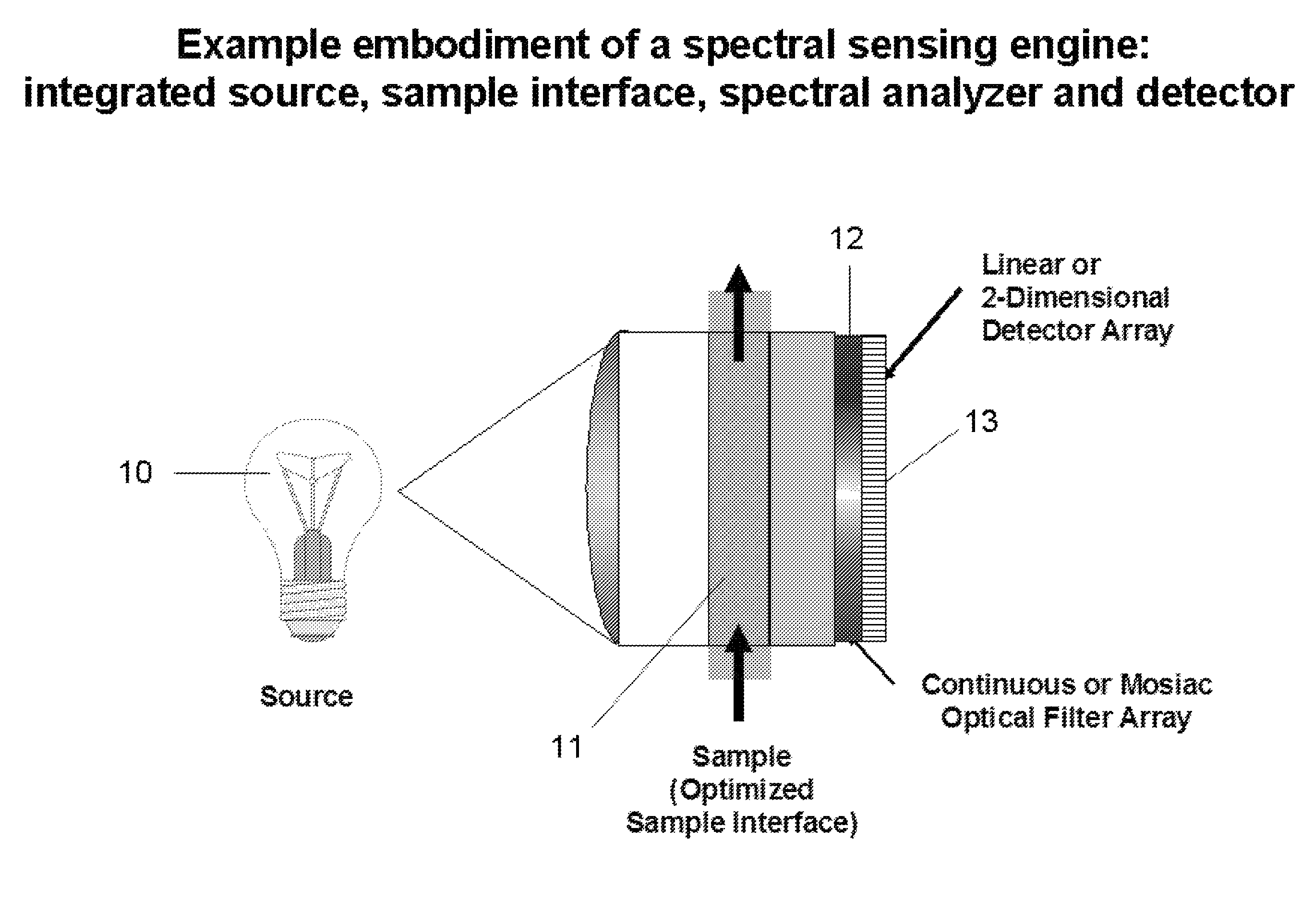
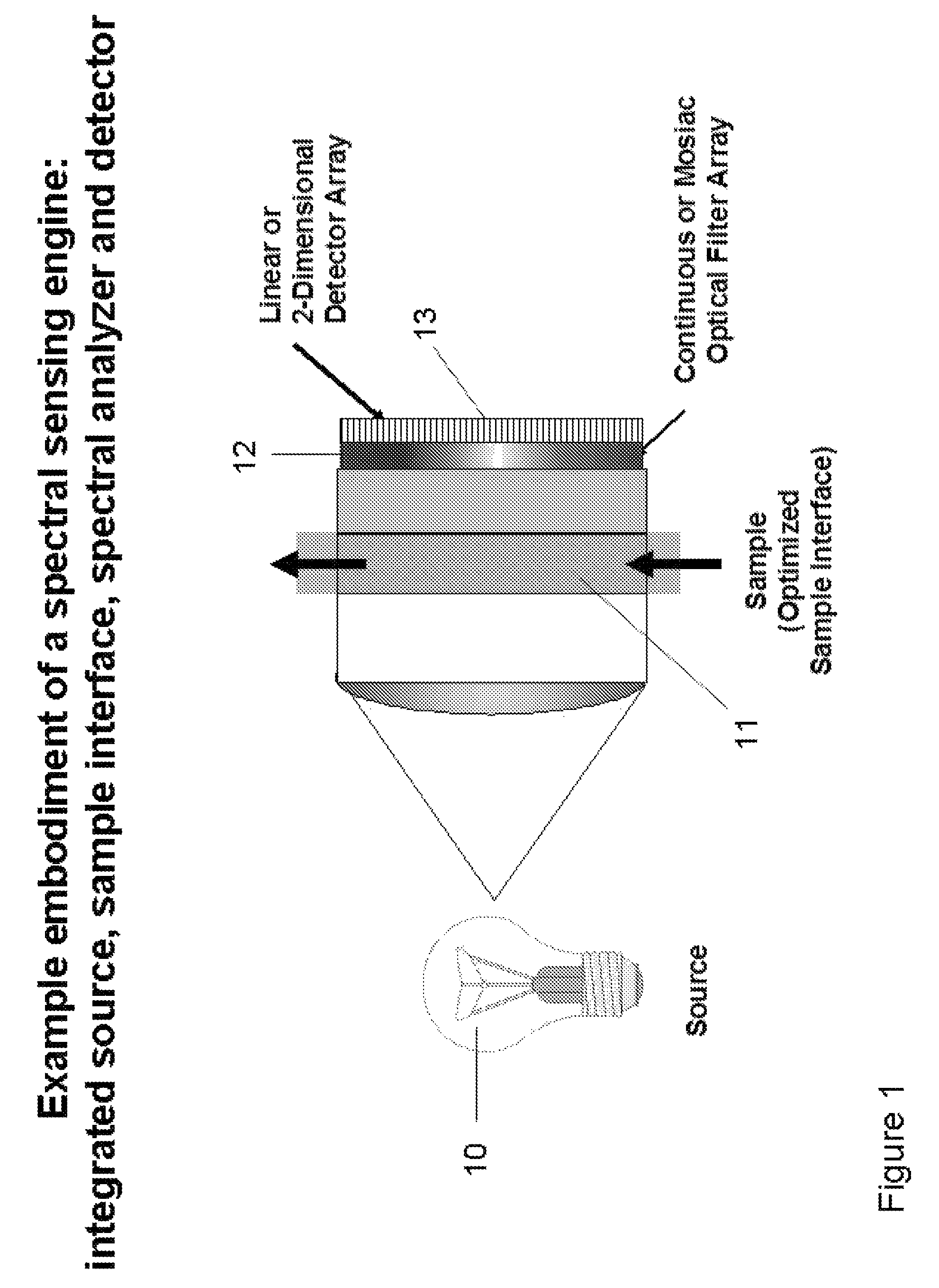
[0036]The present invention is an integrated handheld measurement system for spectral sensing of aqueous and organic solutions, certain gases and vapors, and for certain solid substrates, such as powders and extended solid surfaces. The sensing aspect of this invention preferably includes one or more miniaturized optical spectral sensors located within the body of the handheld device. Several different embodiments are described for the body of the device, and examples are cited later in FIGS. 6 to 13. FIG. 1 provides a symbolic representation of an example spectral sensing system, comprising a light or energy source 10, an optimized and integrated sample chamber 11, a spectral analyzer or spectrally selective element 12, and an integrated detection system 13. Example embodiments of such spectral sensing systems are illustrated in FIGS. 4 to 10. In the configuration shown in FIG. 1, the source is indicated as an incandescent-style of source, such as a tungsten source. The invention c...


PUM


Abstract

An integrated spectral sensing engine featuring energy sources and detectors within a single package includes sample interfacing optics and acquisition and processing electronics. The miniaturized sensor is optimized for specific laboratory and field-based measurements by integration into a handheld format. Design and fabrication components support high volume manufacturing. Spectral selectivity is provided by either continuous variable optical filters or filter matrix devices. The sensor's response covers the range from 200 nm to 25 μm based on various solid-state detectors. The wavelength range can be extended by the use of filter-matrix devices. Measurement modes include transmittance / absorbance, turbidity (light scattering) and fluorescence (emission). On board data processing includes raw data acquisition, data massaging and the output of computed results. Sensor applications include water and environmental, food and beverage, chemical and petroleum, and medical analyses. These can be expanded into various field and consumer-based applications.

Description

CROSS REFERENCE TO RELATED APPLICATIONS[0001]This application is a divisional application of co-pending application Ser. No. 11 / 605,869, filed on Nov. 29, 2006, which is a continuation-in-part of application Ser. No. 11 / 355,908, filed on Feb. 16, 2006, (now abandoned) which is a continuation-in-part of application Ser. No. 10 / 913,819, filed on Aug. 6, 2004 (now U.S. Pat. No. 7,057,156), which in turn claims priority under 35 U.S.C. §119(e) from provisional patent application Ser. No. 60 / 494,977, filed on Aug. 14, 2003. This application also claims priority under 35 U.S.C. §119(e) from provisional patent application 60 / 740,850 filed on Nov. 30, 2005.FIELD OF THE INVENTION[0002]The present invention relates to a miniaturized integrated spectral sensor, with integrated sensed signal conditioning, signal exchange, and integration into a handheld device for the measurement of solution and solvent-based chemistries. With adaptation, the device can be configured for solids or gases, but li...

Claims


Application Information

Patent Timeline
Patent Type & Authority Patents(United States)
IPC IPC(8): G01J3/51
CPCG01J3/02G01N21/8483G01J3/0264G01J3/0267G01J3/0272G01J3/0291G01J3/2803G01J3/51G01J3/513G01N21/255G01N21/4738G01N21/645G01N21/85G01J3/0259G01N21/274G01N2021/6417G01N2035/1062
Inventor COATES, JOHN
Owner APPELL GEORGE N
Why Eureka
Try Eureka