Power steering apparatus
a technology of steering apparatus and steering wheel, which is applied in the direction of non-deflectable wheel steering, underwater vessels, and registering/indicating the working of vehicles, etc., can solve the problems that the deterioration of steering feeling cannot be prevented sufficiently, and the abrupt change of steering force cannot be suppressed. , to achieve the effect of preventing a deterioration of steering feeling and suppressing an abrupt change of steering for
- Summary
- Abstract
- Description
- Claims
- Application Information
AI Technical Summary
Benefits of technology
Problems solved by technology
Method used
Image
Examples
first embodiment
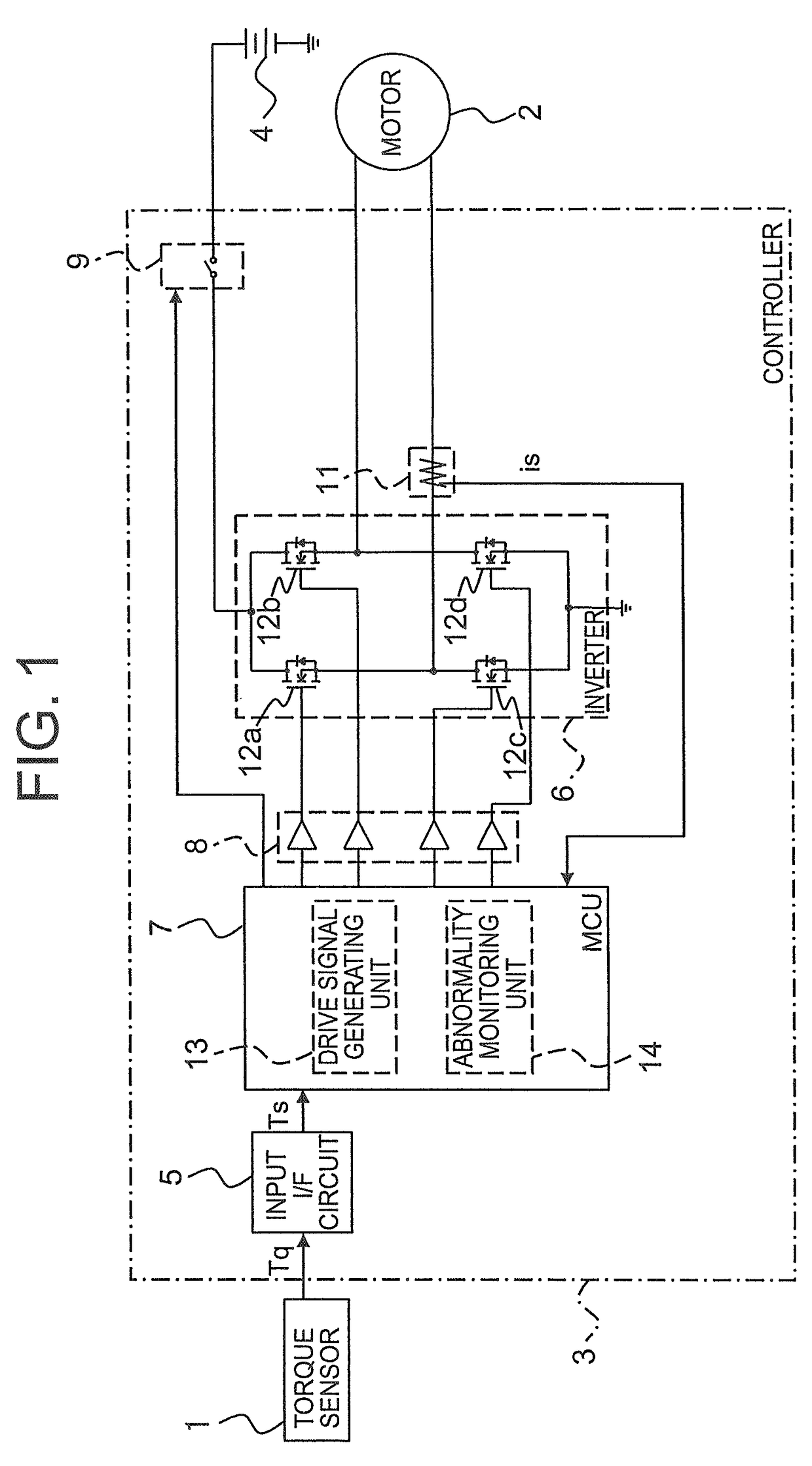
[0028]FIG. 1 is a schematic diagram showing a power steering apparatus according to the first embodiment of the present invention.
[0029]Referring to FIG. 1, the power steering apparatus is equipped with a torque sensor 1 (a steering force detecting unit) for detecting a steering force Tq of a driver of a vehicle, a two-phase DC motor 2 (an electric motor) (hereinafter abbreviated as “the motor 2”) of a permanent magnet field type for supplementing the steering force Tq of the driver, a controller 3 (a control unit) for controlling the driving of the motor 2, and a battery 4 for supplying the controller 3 with electric power.
[0030]The steering force Tq detected by the torque sensor 1 is input to the controller 3. The motor 2 is driven under the control of the controller 3 to apply a torque to a steering system (not shown) of the vehicle.
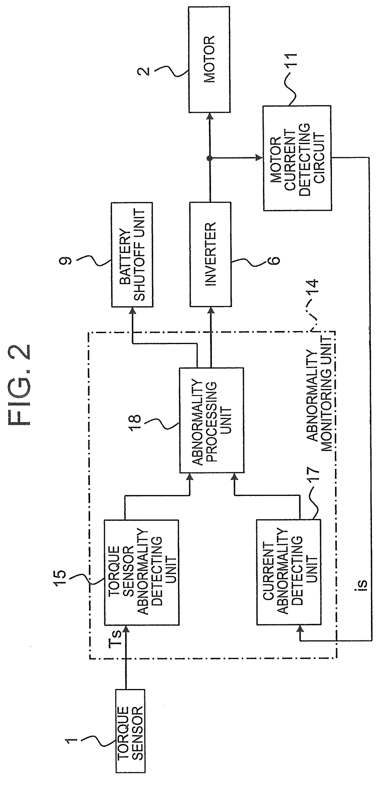
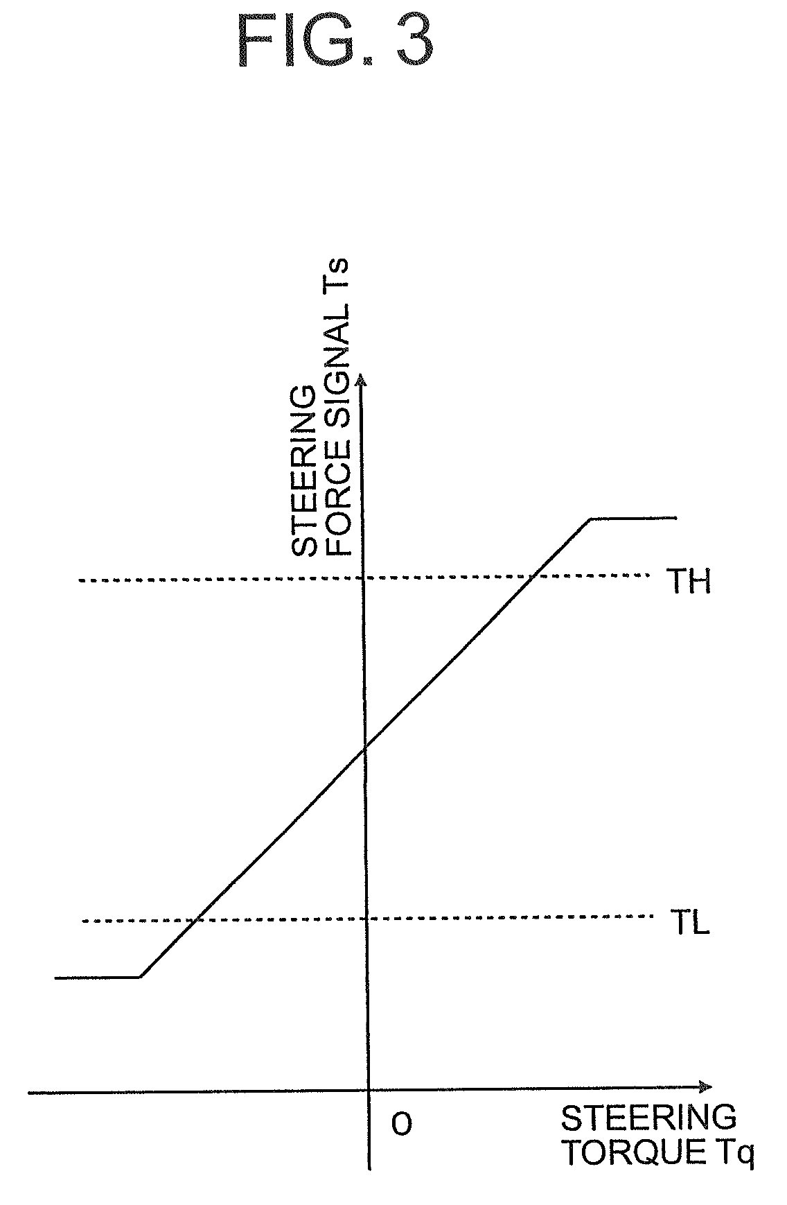
[0031]The controller 3 includes an input interface circuit 5, an inverter 6, a microcomputer 7 (hereinafter abbreviated as “an MCU (abbreviation of m...
second embodiment
[0063]In the aforementioned first embodiment of the present invention, the FET elements 12a to 12d of the inverter 6 are operated to constitute the closed-loop circuit. However, the present invention is not limited to this configuration. It is also appropriate to provide a short-circuiting unit such as a relay between the input terminals of the motor 2 and short-circuit the short-circuiting unit to constitute the closed-loop circuit including the motor 2 when an abnormal state of the torque sensor 1 is detected.
[0064]Description of the components identical to those of the first embodiment will be omitted.
[0065]FIG. 5 is a schematic diagram showing a power steering apparatus according to the second embodiment of the present invention.
[0066]Referring to FIG. 5, a controller 3A further includes a motor short-circuiting unit 19 (a short-circuiting unit) provided between the motor 2 and the inverter 6.
[0067]The motor short-circuiting unit 19 short-circuits the input terminals of the moto...
third embodiment
[0089]In the aforementioned first embodiment of the present invention and the aforementioned second embodiment of the present invention, the two-phase DC motor is employed to constitute the power steering apparatus. However, the present invention is not limited to this construction. The motor may also be designed as a three-phase DC motor.
[0090]Description of the components identical to those of the first embodiment will be omitted.
[0091]FIG. 8 is a schematic diagram showing a power steering apparatus according to the third embodiment of the present invention.
[0092]Referring to FIG. 8, the power steering apparatus is further equipped with a rotational angle sensor 20 for detecting a rotational angle θr of a rotor (not shown) of a motor 2B. The motor 2B is designed as a three-phase DC brushless motor of a permanent magnet field type.
[0093]A controller 3B further includes an input interface circuit 21. The input interface circuit 21, to which the rotational angle θr output by the rota...
PUM
 Abstract
Description
Claims
Application Information
 - R&D
- Intellectual Property
- Life Sciences
- Materials
- Tech Scout
- Unparalleled Data Quality
- Higher Quality Content
- 60% Fewer Hallucinations
Browse by: Latest US Patents, China's latest patents, Technical Efficacy Thesaurus, Application Domain, Technology Topic, Popular Technical Reports.
© 2025 PatSnap. All rights reserved.Legal|Privacy policy|Modern Slavery Act Transparency Statement|Sitemap|About US| Contact US: help@patsnap.com


