Sensor and method for measuring position and speed

a sensor and position technology, applied in the direction of fluid speed measurement, speed measurement using gyroscopic effects, instruments, etc., can solve the problem that existing sensors are rather inaccurate in measuring the position of a fast-moving target, and achieve the effect of limiting the sensitivity of the sensor

Inactive Publication Date: 2011-03-15
HUTCHINSON SA
View PDF10 Cites 4 Cited by
  • Summary
  • Abstract
  • Description
  • Claims
  • Application Information

AI Technical Summary

Benefits of technology

[0032]the use of a target made of materials of different conductivities ma...

Problems solved by technology

However, shortening the observation period is detrimental to the elimination of additive noi...

Method used


Image

  • Sensor and method for measuring position and speed
  • Sensor and method for measuring position and speed
  • Sensor and method for measuring position and speed

Examples


Embodiment Construction

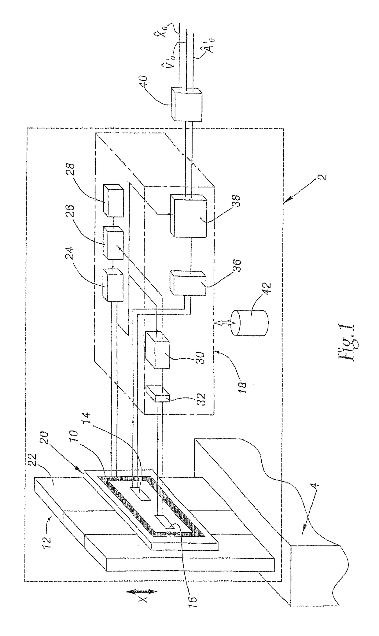
[0039]FIG. 1 represents a sensor 2 of the position and of the speed of a movable part 4.

[0040]Here, by way of illustration, the part 4 moves in translation in a vertical direction represented by the arrow X.

[0041]The sensor 2 comprises:[0042]an inductor 10 suitable for inducing a periodic or alternating magnetic excitation field;[0043]a target 12 made of conducting materials that is suitable for modifying as a function of its position within the magnetic excitation field;[0044]a transducer 14 suitable for transforming the magnetic field modified by the target 12 into an electrical measurement signal;[0045]a reference transducer 16 suitable for transforming solely the modifications of the magnetic excitation field that are independent of the displacement of the target 12 in the direction X into an electrical reference signal; and[0046]a signal excitation and processing circuit 18, linked to the inductor 10 and to the transducers 14 and 16.

[0047]The part 4 and the target 12 are fixed ...


PUM


Abstract

A sensor for detecting the position and speed of a part mobile along at least one measurement direction includes an estimator (38) adapted to provide estimation of position and speed based on a displacement model of the target during a period of observation Tobs, the model relating the position of the target at a time t included in the period of observation Tobs, at least to the position and the speed to be estimated.

Description

BACKGROUND OF THE INVENTION[0001]The present invention relates to a sensor and a method for measuring position and speed.DESCRIPTION OF THE RELATED ART[0002]There exist sensors of position and speed of a movable part comprising:[0003]at least one excitation inductor suitable for inducing a magnetic excitation field as a function of an excitation current or voltage of this inductor,[0004]at least one target made of conducting or magnetic material suitable for modifying as a function of its position the magnetic excitation field, this target being secured to the movable part,[0005]at least one first transducer suitable for transforming the magnetic field modified by the target into an electrical measurement signal, and[0006]a first estimator able to estimate, on completion of an observation period Tobs, the position and the speed of the target on the basis of N samples of the electrical measurement signal and of N samples of the excitation current and / or voltage, these samples being t...

Claims


Application Information

Patent Timeline
IPC IPC(8): G01P11/00G01C17/00
CPCG01D5/147G01D5/2046G01D5/2053
Inventor LENGLET, LUC LUCIEN MARIE
Owner HUTCHINSON SA
Why Eureka
Try Eureka