Infrared lens, infrared camera, and night vision

a technology of infrared camera and infrared lens, which is applied in the field of infrared lens, can solve the problems of poor imaging performance, high processing cost, and concern of increasing distortion in wide angle region, so as to minimize the thickness of the respective lens, improve imaging performance, and minimize light loss

Inactive Publication Date: 2011-03-22
SUMITOMO ELECTRIC IND LTD
View PDF31 Cites 6 Cited by
  • Summary
  • Abstract
  • Description
  • Claims
  • Application Information

AI Technical Summary

Benefits of technology

[0032]According to the first invention, the entire lens is made of low-cost zinc sulfide, and the entire lenses are configured by at least the first and second lens groups having positive refractive power. Therefore, it is possible to improve an imaging performance while minimizing the light loss at the time of transmission through the lenses by minimizing thicknesses of the respective lenses, and thus it is possible to provide the infrared lens forming a bright image, and having a high imaging performance by using a configuration of low cost.
[0033]According to the second invention, it is possible to effectively improve chromatic aberration which is a main issue in the infrared lens.
[0034]According to the third invention, the aspheric surface is formed on the first lens group of which an aperture is large and the spherical aberration easily occurs, and thus it is possible to effectively improve the aberration.
[0035]Since the lenses included in the first lens group have largest diameter, the aspheric surface is formed on the first lens group. Therefore, a degree of a shape change of the aspheric surface (a degree of undulation) decreases relative to the case where the aspheric surface is formed on another lens and the mold fabrication and lens process are easy to perform.
[0036]According to the fourth invention, by satisfying these conditions, various aberrations (which include the distortion in the wide angle region) within the field of vision are corrected so as to have balance, and it is possible to easily embody the compact and bright infrared lens 2a.
[0037]According to the fifth invention, the whole infrared lens is configured by the three positive meniscus lens of which convex surfaces are opposed to the object. Therefore, it is possible to improve an imaging performance while minimizing the light loss at the time of transmission through the zinc sulfide lenses of by minimizing lens thicknesses. It is also possible to provide the infrared lens forming a bright image, and having a high imaging performance by using a configuration of low cost.

Problems solved by technology

Patent Document 1: Japanese Unexamined Patent Application it can not be said that an MTF (Modulation Transfer Function) obtainable from the exemplary configuration disclosed in the Patent Document 1 is sufficient, and there is a problem of poor imaging performance.
Besides, there is a concern of increasing distortion in a wide angle region (for example, in the region where a view angle is 20° or more).
Since the infrared lens described in Patent Document 1 is produced by a cutting process, there is also a problem of high processing cost.

Method used


Image

  • Infrared lens, infrared camera, and night vision
  • Infrared lens, infrared camera, and night vision
  • Infrared lens, infrared camera, and night vision

Examples


embodiment 1

Basic Configuration

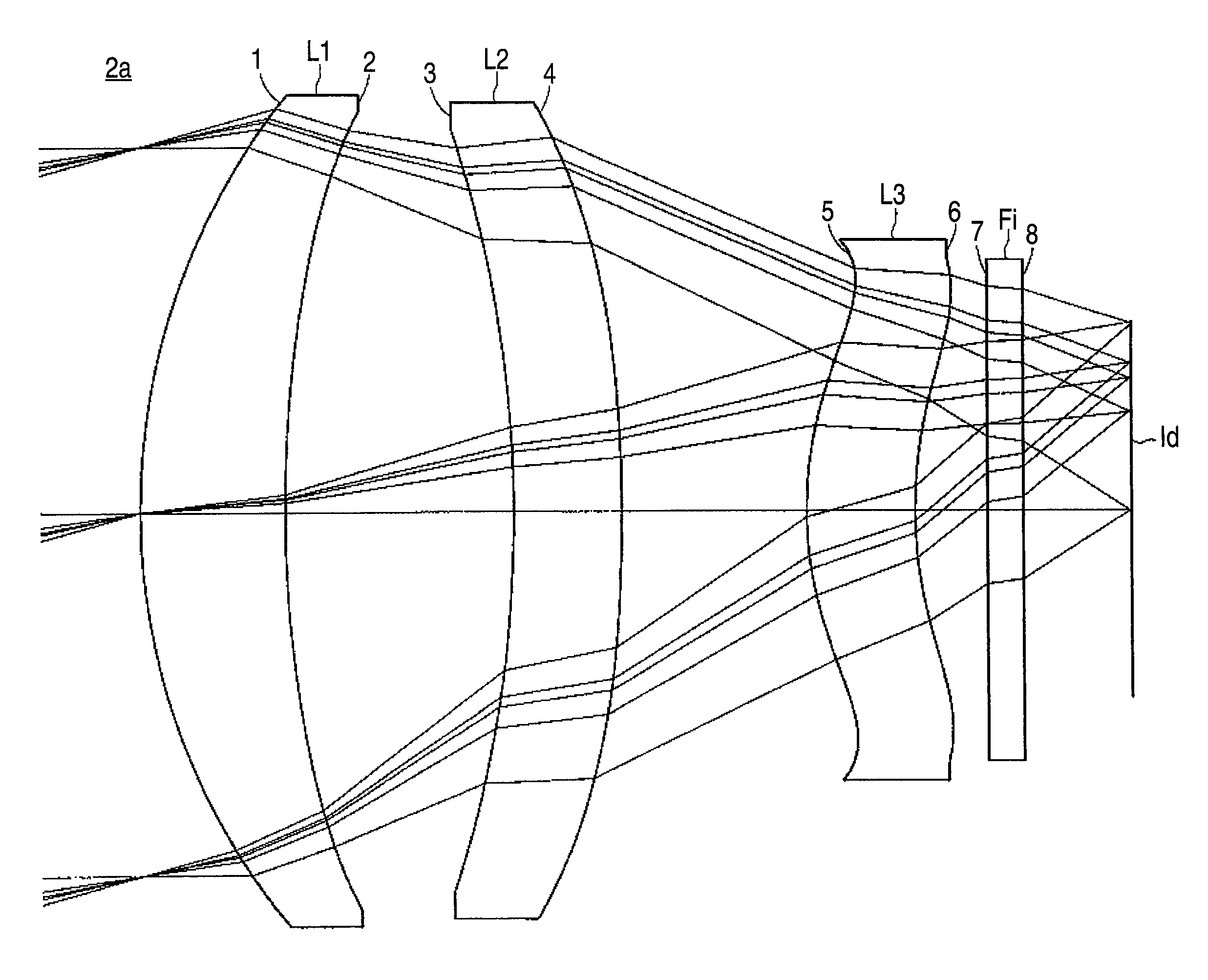
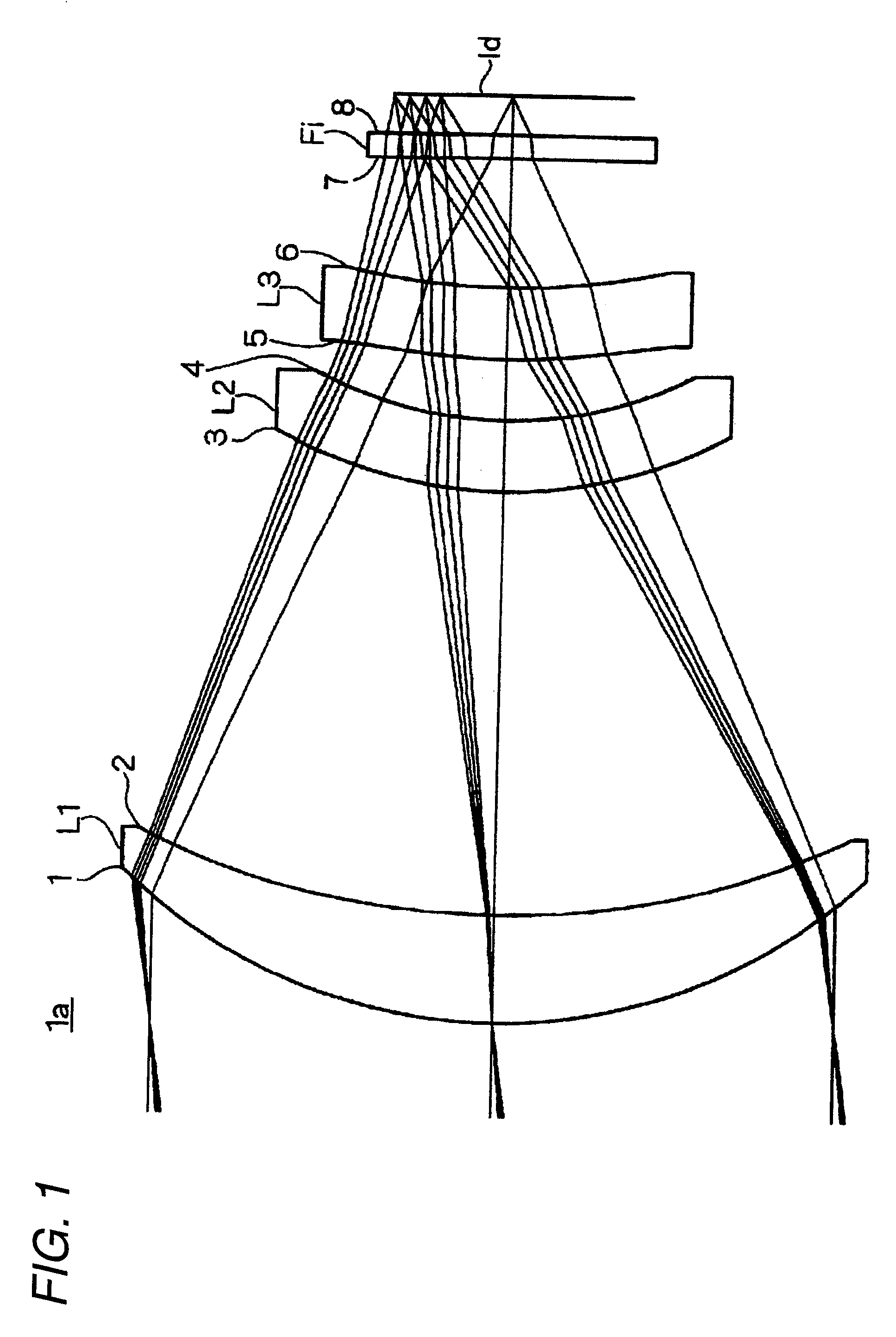
[0212]Hereinafter, a basic configuration of an infrared lens according to Embodiment 1 of the invention will be described with reference to FIG. 1. In this section, it will be described about only the basic configuration of the infrared lens 1a shown in FIG. 1, and a further detailed configuration thereof will be described as Example in the following section.

[0213]The infrared lens 1a including first to third lenses L1 to L3 which are made of zinc sulfide are arranged in this order from an object side as shown in FIG. 1. The first to third lenses L1 to L3 are configured as a positive meniscus lens of which convex surfaces are opposed to the object side, and these first to third lenses L1 to L3 are configured as the first to third lenses' groups relating to the invention, respectively. Light (infrared rays) transmitted through lenses L1 to L3 is incident on an acceptance surface of an imaging device Id through an infrared transmission window Fi, and the light forms...

example 1-1

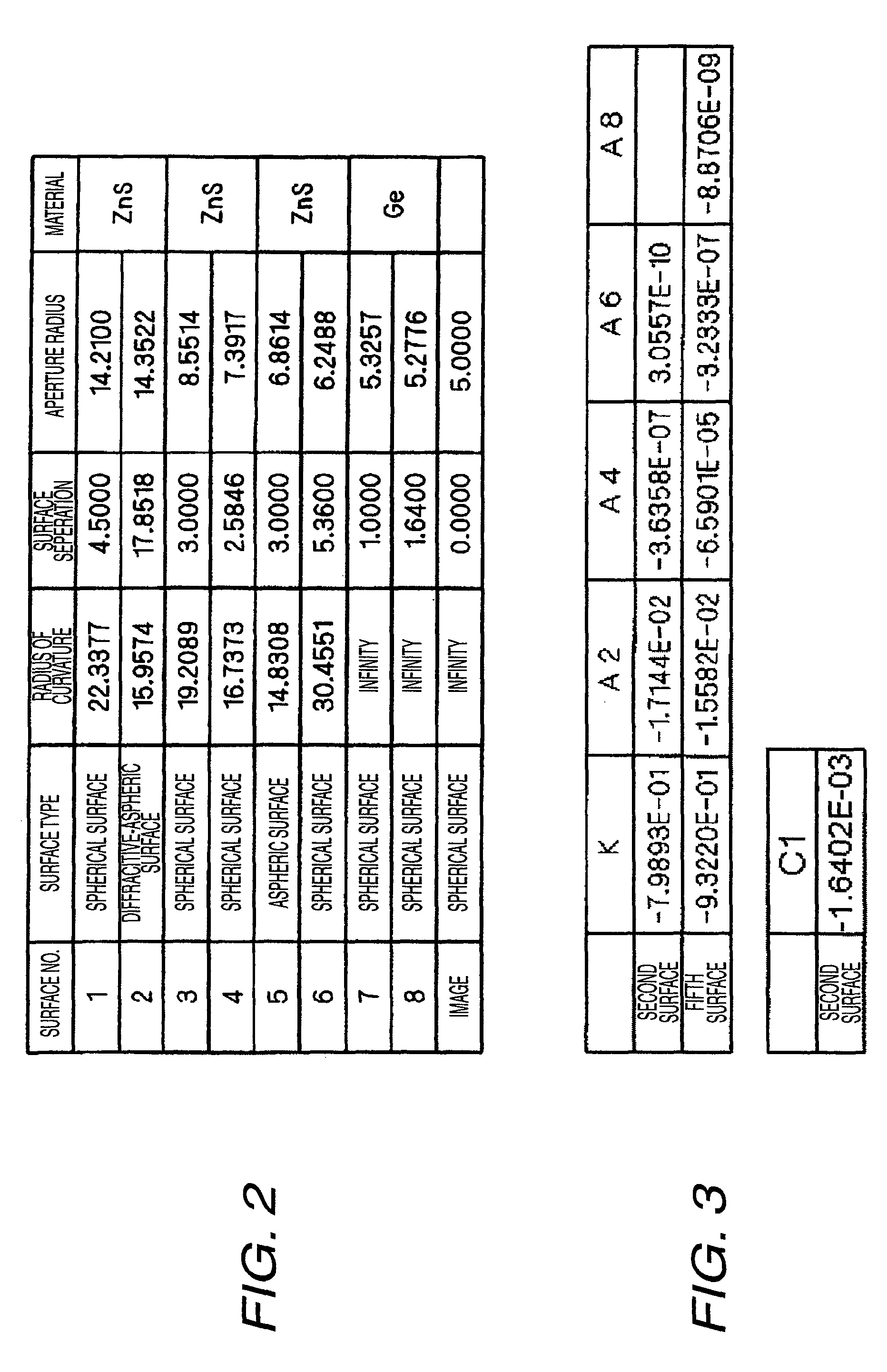
[0233]The infrared lens 1a according to Example 1-1 have configurations illustrated in the FIGS. 1 to 3, and the lenses are configured that the f1 / f is 1.10, the F value is 1.1, the maximum diameter is 28.4 mm, and the view angle is 17° (the view angle is set in the combination case where the imaging device has a pixel pitch 25 μm and a pixel size 320×240). The aspheric surface shape (diffractive surface shape) of a second surface and a fifth surface shown in FIG. 3 is determined by substituting the parameter into the following expression (ditto below):

[0234]Z⁡(y)=y2R1+1-(1+K)⁢y2R2+A⁢⁢2·y2+A⁢⁢4·y4+A⁢⁢6·y6+A⁢⁢8·y8+…+Φ⁡(y)[Numerical⁢⁢Formula⁢⁢1]⁢Φ⁡(y)=1N-1·mod⁡(C⁢⁢1·y2,-λ)[Numerical⁢⁢Formula⁢⁢2]

[0235]In the formula, the Z is a length (mm) of a perpendicular line down on the tangential surface in contact with the top of the aspheric surface from a point on the aspheric surface, the y is a height (mm) from an optical axis, the K is an eccentricity, the R is a near-axis curvature radius,...

example 1-2

[0238]The infrared lens 1b according to Example 1-2 have configurations illustrated in FIGS. 15 to 17, and the lenses are configured that the f1 / f is 1.40, the F value is 1.0, the maximum diameter is 25.9 mm, and the view angle is 20°.

[0239]MTF characteristics with respect to wavelengths 8 μm, 10 μm, and 12 μm within view angles (0°, 6.0°, 7.5°, and 8.5°) in the configuration of Example 1-2 are illustrated in FIGS. 18 to 24. Additionally, the spherical aberration, astigmatism, distortion, and longitudinal aberration characteristics with respect to the wavelengths 8 μm, 10 μm, and 12 μm are illustrated in FIGS. 25 to 27 and FIGS. 28(a) to 28(e).


PUM


Abstract

An infrared lens 1a includes first to third lenses L1 to L3 which are made of zinc sulfide and arranged in this order from an object side. Each of the first to third lenses L1 to L3 is configured as a positive meniscus lens of which convex surface is opposed to the object. The lenses L1 to L3 are formed by heat-press molding raw powder of zinc sulfide using a lens-shaped mold. In addition, a concave surface (the surface opposed to the image side) of the first lens L1 is formed as a diffractive surface.

Description

CROSS-REFERENCE TO RELATED APPLICATIONS[0001]This application is a Continuation of U.S. application Ser. No. 11 / 919,754, filed on Nov. 1, 2007 now U.S. Pat. No. 7,738,169, which is a U.S. National Phase under 35 U.S.C. §371 of International Application No. PCT / JP2006 / 322195, filed Nov. 7, 2006, claiming priority of Japanese Patent Application No. 2006-020411, filed on Jan. 30, 2006 and Japanese Patent Application No. 2006-065401, filed on Mar. 10, 2006 the entire contents of each of which are hereby incorporated by reference.TECHNICAL FIELD[0002]The present invention relates to an infrared lens (more particularly, a far infrared lens), an infrared camera and a night vision.BACKGROUND ART[0003]An infrared lens using zinc sulfide as lens material is described in Patent Document 1.[0004]Patent Document 1: Japanese Unexamined Patent Application it can not be said that an MTF (Modulation Transfer Function) obtainable from the exemplary configuration disclosed in the Patent Document 1 is ...

Claims


Application Information

Patent Timeline
Patent Type & Authority Patents(United States)
IPC IPC(8): G02B13/14
CPCG02B13/14G02B1/041G02B9/16G02B13/0035G02B13/18
Inventor IZUMI, TATSUYAHIRAIWA, CHIHIRO
Owner SUMITOMO ELECTRIC IND LTD
Why Eureka
Try Eureka