Laser apparatus, laser irradiation method, and manufacturing method of semiconductor device
a laser irradiation method and laser irradiation technology, applied in lasers, manufacturing tools, active medium materials, etc., can solve the problems of difficult accurate generation, over-method limit, and so as to improve stability, suppress laser medium pressure fluctuation, and improve the effect of light gathering
- Summary
- Abstract
- Description
- Claims
- Application Information
AI Technical Summary
Benefits of technology
Problems solved by technology
Method used
Image
Examples
embodiment mode 1
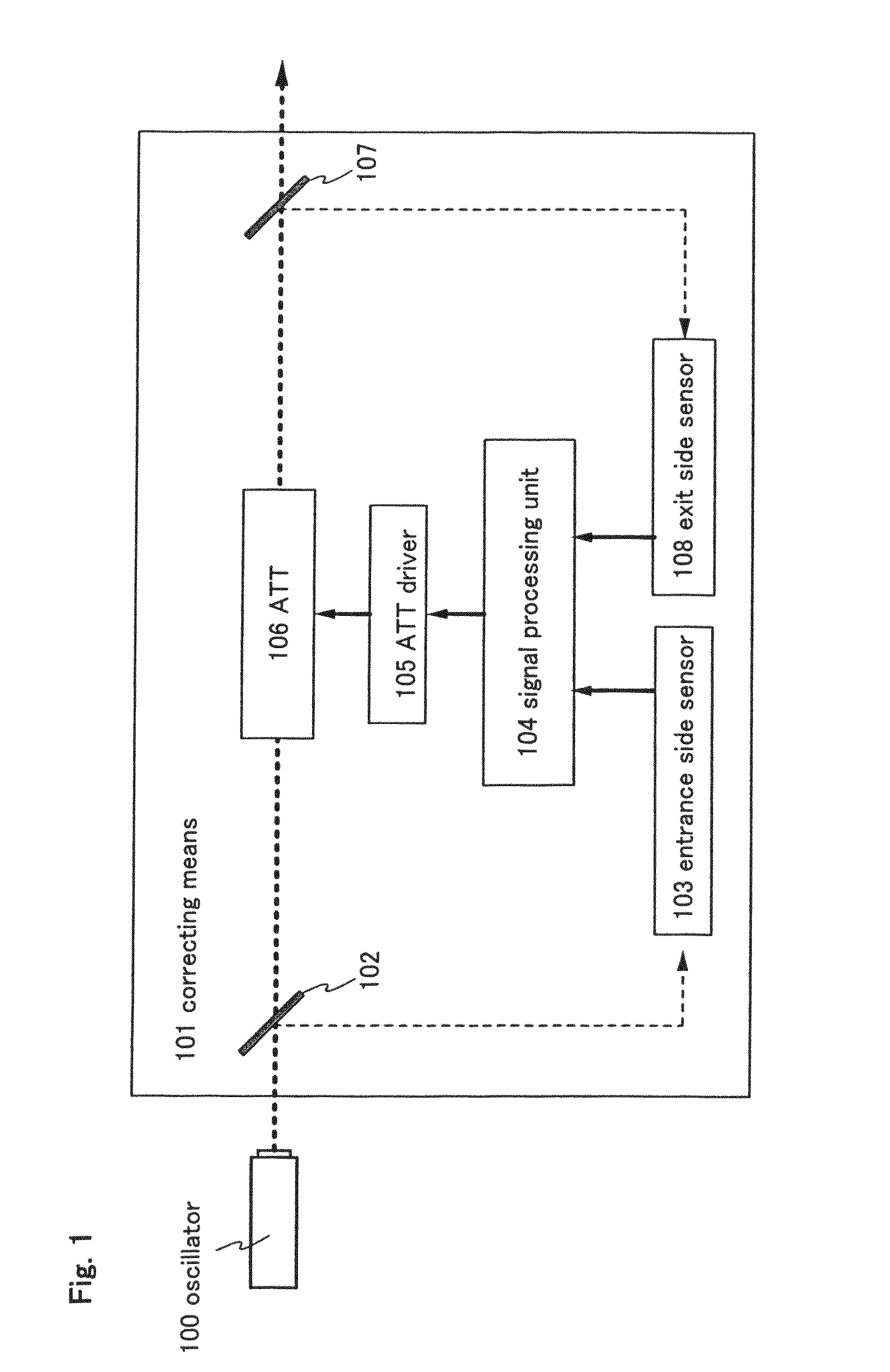
[0061]FIG. 1 is a block diagram of correcting means 101 of this embodiment mode. The correcting means 101 shown in FIG. 1 has an entrance side optical system 102, an entrance side sensor 103, a signal processing unit 104, an ATT driver 105, an ATT 106, an exit side optical system 107, and an exit side sensor 108.
[0062]The correcting means 101 shown in FIG. 1 samples laser beam on the entrance side of the ATT 106 and laser beam on the exit side of the ATT 106 both. Therefore, one optical system and one sensor are provided for sampling on each of the entrance side and the exit side. In FIG. 1, the entrance side optical system and the exit side optical system are discriminated from each other by denoting the former by reference symbol 102 and the latter by 107. The entrance side sensor and the exit side sensor are discriminated from each other by denoting the former by reference symbol 103 and the latter by 108.
[0063]The entrance side and the exit side are controlled by the same signal...
embodiment mode 2
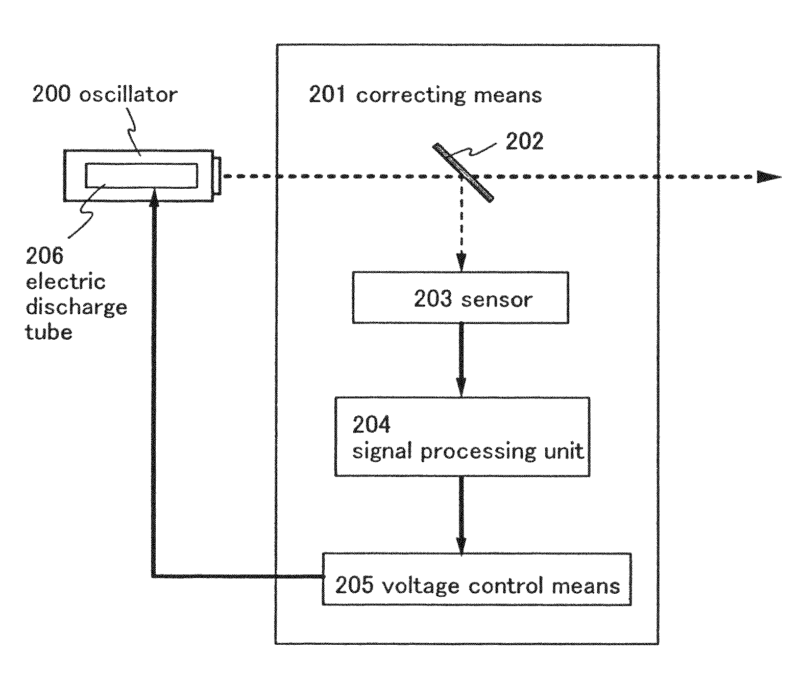
[0089]FIG. 6 is a block diagram of correcting means 201 of this embodiment mode. The correcting means 201 shown in FIG. 6 has an optical system 202, a sensor 203, a signal processing unit 204, a voltage controlling means 205, and an electric discharge tube 206.
[0090]The correcting means 201 shown in FIG. 6 uses the optical system 202 to sample a part of laser beam emitted from the oscillator 200. The laser beam then enters the sensor 203, where the partial incident laser beam is converted into an electric signal. The electric signal is inputted to the signal processing unit 204. The sensor 203 can be any photoelectric conversion element as long as it is capable of generating an electric signal that contains laser beam energy fluctuation as data.
[0091]The signal processing unit 204 performs signal processing on the electric signal inputted. Out of energy fluctuation of the laser beam, periodic fluctuation is analyzed. For the signal processing, fast Fourier transformation and other v...
embodiment 1
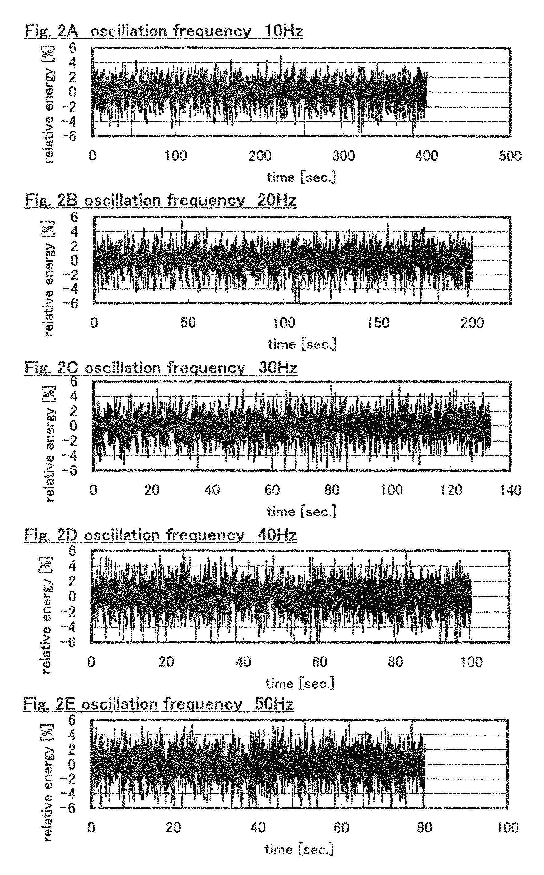
[0101]Periodic fluctuation of laser beam energy varies depending on the oscillation frequency of an oscillator. This embodiment gives a description on the relation between the oscillation frequency of laser beam emitted from an excimer laser oscillator and the frequency of periodic fluctuation.
[0102]FIG. 7 shows the relation between the laser beam oscillation frequency (Hz) and the highest peak frequency (Hz) obtained by Fourier transformation. The horizontal axis indicates the oscillation frequency (Hz), and the vertical axis indicates the peak position (Hz) after Fourier transformation. Although measurements have been taken on different days, equal measurement conditions have been used except the oscillation frequency.
[0103]The peak frequency obtained by Fourier transformation means the frequency of periodic fluctuation of laser beam energy. The frequency of the periodic fluctuation repeatedly rises and drops in stages. Specifically, the frequency of the periodic fluctuation reach...
PUM
 Abstract
Description
Claims
Application Information
 - R&D
- Intellectual Property
- Life Sciences
- Materials
- Tech Scout
- Unparalleled Data Quality
- Higher Quality Content
- 60% Fewer Hallucinations
Browse by: Latest US Patents, China's latest patents, Technical Efficacy Thesaurus, Application Domain, Technology Topic, Popular Technical Reports.
© 2025 PatSnap. All rights reserved.Legal|Privacy policy|Modern Slavery Act Transparency Statement|Sitemap|About US| Contact US: help@patsnap.com


