Two-axis direct fluid shear stress sensor

a shear stress sensor and two-axis technology, applied in the field of shear stress sensors, can solve the problems of floating heads, high-speed flows, and flows associated with combustion and/or impinging shocks, and achieve the effect of facilitating the pivotal movement of the pla

Inactive Publication Date: 2011-04-12
NASA
View PDF15 Cites 16 Cited by
  • Summary
  • Abstract
  • Description
  • Claims
  • Application Information

AI Technical Summary

Problems solved by technology

Although all of these techniques can be shown to accommodate some flow regimes, indirect methods have not been shown to be reliable for complex flows, high-speed flows, or flows associated with combustion and / or impinging shocks.
The forces are very small, sometimes requiring large floating heads and expensive instrumentation to obtain accurate results.
These floating sensors are exposed to the fluid flow and thus are not suitable for extreme or hostile conditions and often require complex optical or capacitive transduction techniques.
However, the performance of this sensor suffers from front-side electrical contacts that interfere with fluid flow past the sensor and / or from remote mounting of the incident light source.
Both direct and indirect principles for sensing this shear force and sensors employing these exist with the direct methods being favored, however no commercial devices are readily available.
The demands of sensors for aerodynamic application are in particular very challenging to meet as the forces involved are small (few Pascal to few hundred Pascal) and the resolution needed is high (few milliPascal) with high spatial resolution (few hundred microns or less) and frequency response from steady state to tens of kilohertz.

Method used


Image

  • Two-axis direct fluid shear stress sensor
  • Two-axis direct fluid shear stress sensor
  • Two-axis direct fluid shear stress sensor

Examples


Embodiment Construction

[0017]A preferred embodiment of the invention and the various features and advantageous details thereof are explained more fully with reference to the accompanying drawings and detailed in the following description. It should be noted that the features illustrated in the drawings are not necessarily drawn to scale and descriptions of well-known components and processing techniques are omitted so as to not unnecessarily obscure the embodiments of the invention. The examples used herein are intended merely to facilitate an understanding of ways in which the embodiments of the invention may be practiced and to further enable those of skill in the art to practice the embodiments of the invention. Accordingly, the examples should not be construed as limiting the scope of the embodiments of the invention.

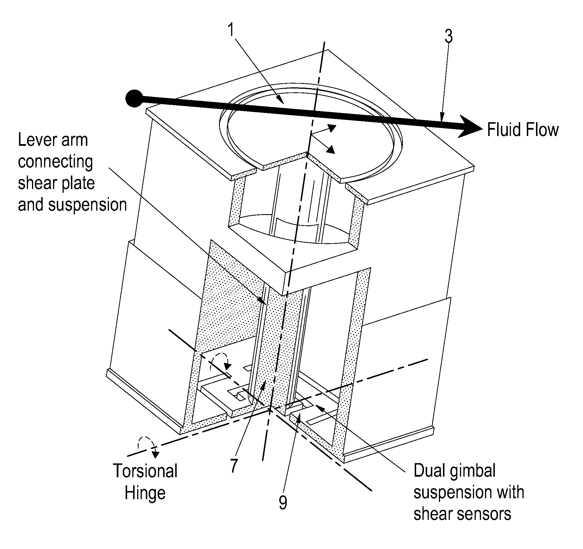
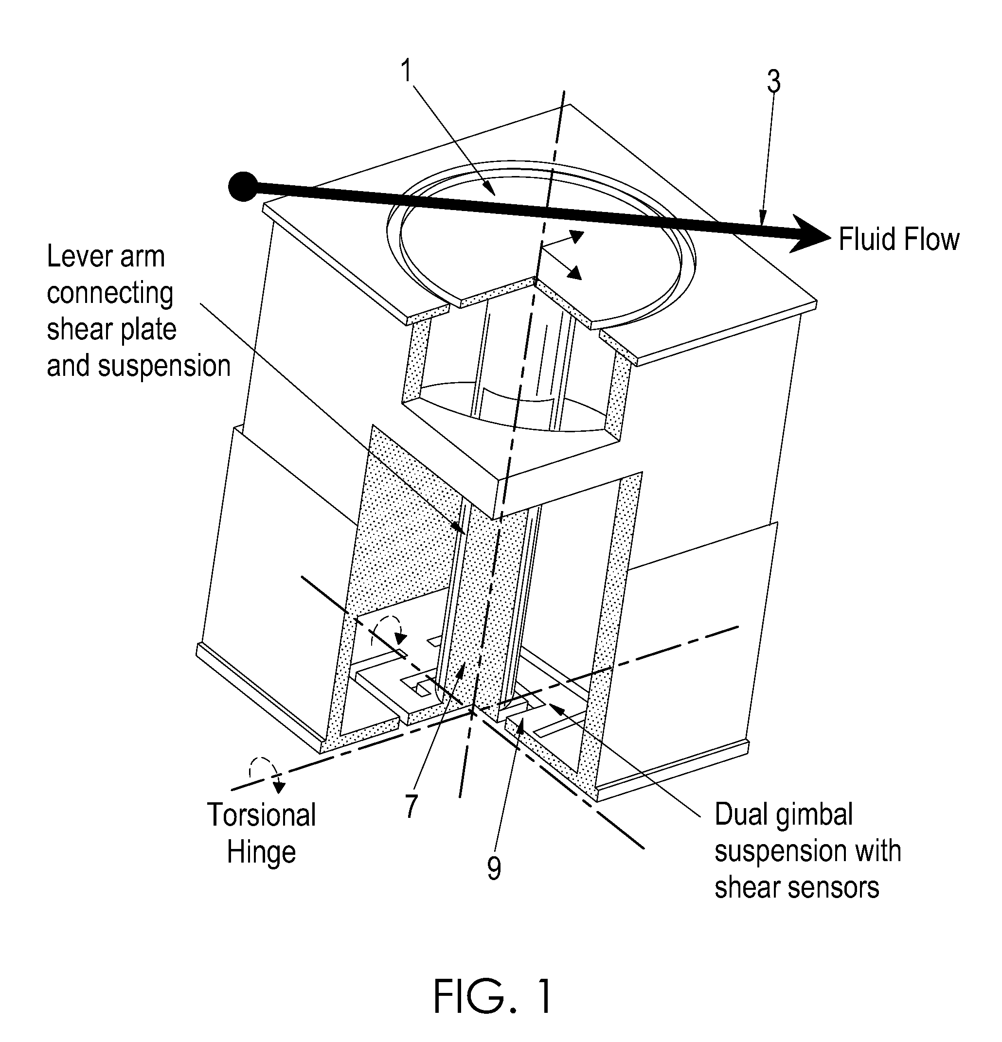
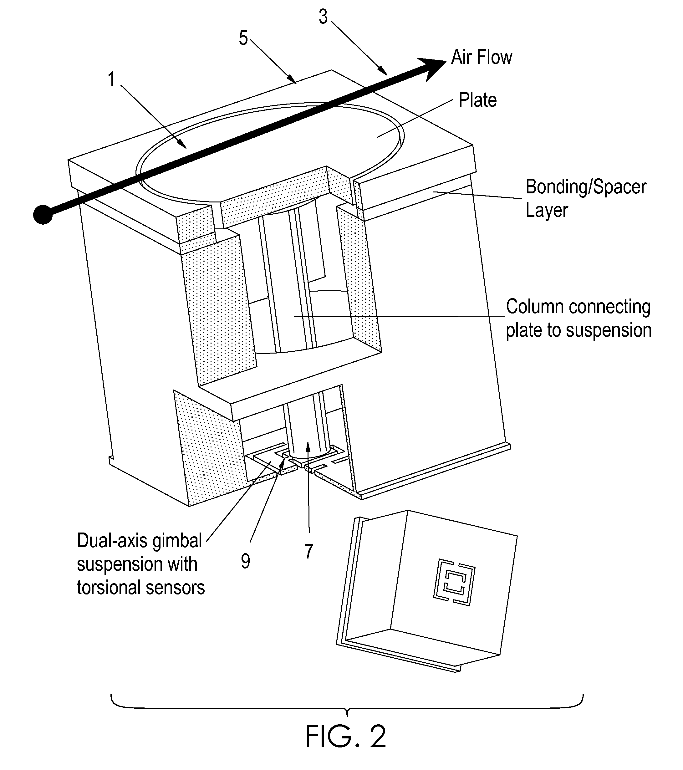
[0018]FIGS. 1-2 depict partial cut away views of the sensor assembly according to the present invention. The sensor includes a shear force collected plate 1 that collects the shear force ...


PUM

PropertyMeasurementUnit
lengthaaaaaaaaaa
diameteraaaaaaaaaa
diameteraaaaaaaaaa

Abstract

A micro sized multi-axis semiconductor skin friction / wall shear stress induced by fluid flow. The sensor design includes a shear / strain transduction gimble connected to a force collecting plate located at the flow boundary surface. The shear force collecting plate is interconnected by an arm to offset the tortional hinges from the fluid flow. The arm is connected to the shear force collecting plate through dual axis torsional hinges with piezoresistive torsional strain gauges. These gauges are disposed on the tortional hinges and provide a voltage output indicative of applied shear stress acting on the force collection plate proximate the flow boundary surface. Offsetting the torsional hinges creates a force concentration and resolution structure that enables the generation of a large stress on the strain gauge from small shear stress, or small displacement of the collecting plate. The design also isolates the torsional sensors from exposure to the fluid flow.

Description

RELATED APPLICATIONS[0001]This application is based upon a prior filed provisional patent application Ser. No. 60 / 991,975 filed Dec. 3, 2007, entitled “A TWO AXIS DIRECT FLUID SHEAR STRESS SENSOR SUITED FOR AERODYNAMIC APPLICATIONS”, the entire subject matter of which is incorporated herein by reference.GOVERNMENT INTEREST[0002]The embodiments of the invention described herein were made by employees of the United States Government, and may be manufactured and used by or for the United States Government for governmental purposes without payment of any royalties thereon or therefor.BACKGROUND OF THE INVENTION[0003]1. Field of the Invention[0004]The present invention relates to shear stress sensors and more particularly to a micro sized multi-axis semiconductor skin friction / wall shear stress sensor / devices.[0005]2. Description of the Related Art[0006]A great number of techniques for the measurement of wall shear stress exist within the prior art, ranging from inferring the skin fricti...

Claims


Application Information

Patent Timeline
Patent Type & Authority Patents(United States)
IPC IPC(8): G01N3/24
CPCG01N3/24G01N2203/0623G01N2203/0254G01L1/18G01L5/162G01N11/00G01N13/00
Inventor BAJIKAR, SATEESHSCOTT, MICHAEL A.ADCOCK, EDWARD E.
Owner NASA
Why Eureka
Try Eureka