Capacitor with sacrificial lead wire configuration and improved manufacturing method thereof

a technology of lead wire and capacitor, which is applied in the direction of fixed capacitor details, casings/cabinets/drawers, electrical apparatus casings/cabinets/drawers, etc., can solve the problems of reducing capacitance, contributing to manufacturing inefficiency and increasing capacitor cost, and significant amount of wasted anode wire material, which is known to be a particularly expensive material, so as to achieve the effect of improving electrical properties

Inactive Publication Date: 2011-04-19
KEMET ELECTRONICS CORP
View PDF16 Cites 28 Cited by
  • Summary
  • Abstract
  • Description
  • Claims
  • Application Information

AI Technical Summary

Benefits of technology

[0011]It is an object of the present invention to provide a capacitor with improved electrical properties.
[0012]It is another object of the present invention to provide a method of manufacturing a capacitor with improved manufacturing efficiencies.
[0013]A particular feature of the present invention is the ability to provide a capacitor with improved volumetric efficiencies.
[0014]Another particular feature of the present invention is a decrease in the amount of waste created and a decrease in the creation of defective product.

Problems solved by technology

Unfortunately, increasing the wire diameter also reduces the capacitance by displacing porous anode body material which would otherwise contribute to capacitance.
Multiple, or large, anode lead wires are a detriment to both aspects.
The use of multiple anode wires is a significant contributor to manufacturing inefficiency and increased capacitor cost.
This creates a significant amount of wasted anode wire material which is known to be a particularly expensive material.
Yet another problem is the defects which occur as a result of cutting the lead wire.
The cutting operation has been determined to be a contributor to current leakage due to the stress created at the intersection of the lead wire and anode body.

Method used


Image

  • Capacitor with sacrificial lead wire configuration and improved manufacturing method thereof
  • Capacitor with sacrificial lead wire configuration and improved manufacturing method thereof
  • Capacitor with sacrificial lead wire configuration and improved manufacturing method thereof

Examples


Embodiment Construction

[0028]The invention will be described with reference to the drawings which form an integral part of the instant disclosure. In the various figures similar elements will be numbered accordingly.

[0029]An improved method for manufacturing a capacitor, and an improved capacitor, is provided by the instant invention.

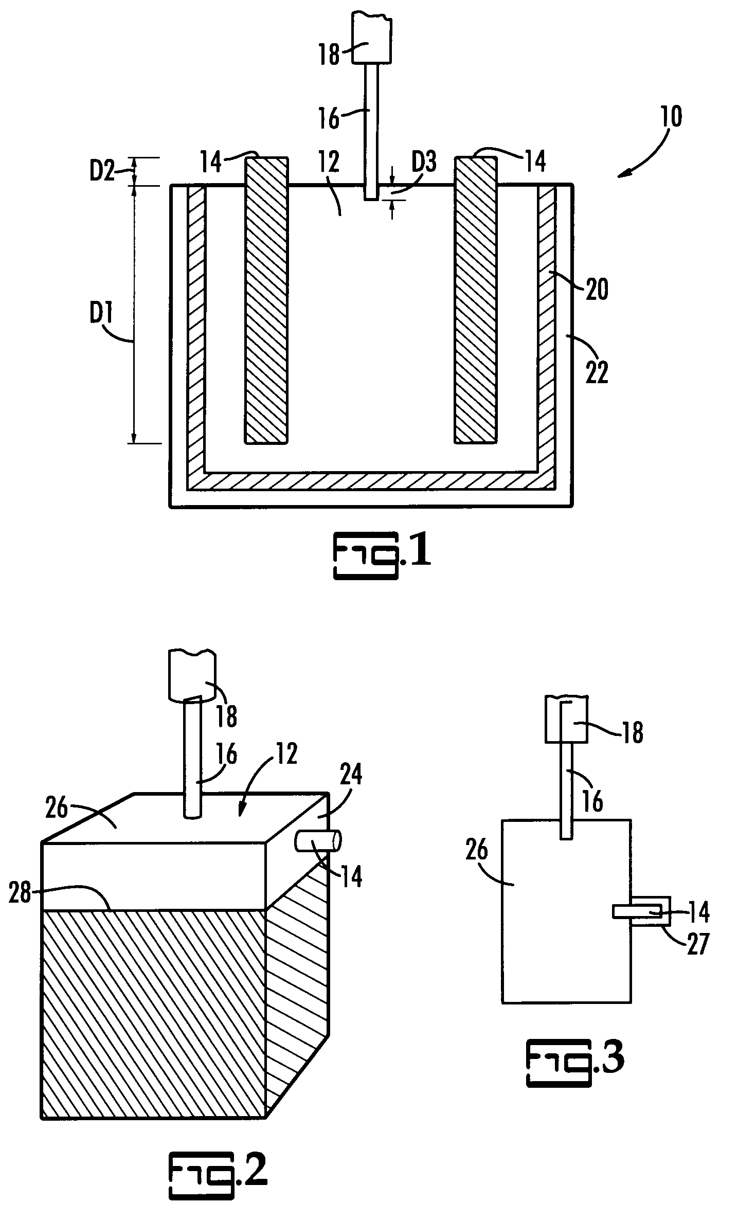
[0030]An embodiment of the present invention is illustrated in cross-sectional schematic view in FIG. 1. In FIG. 1 the capacitor body, generally represented at 10, comprises an anode, 12. Extending from the anode is at least one anode lead wire, 14. The anode lead wire is preferably integral to the anode and extends into the anode a distance, D1. It is preferable that the distance, D1, is as long as possible to insure as much surface area contact between the anode material and the anode lead wire embedded therein. The anode lead wire extends beyond the anode body by a distance, D2, which represents a sufficient amount for attachment of the anode lead wire to a lead frame or c...


PUM

PropertyMeasurementUnit
angleaaaaaaaaaa
angleaaaaaaaaaa
conductiveaaaaaaaaaa

Abstract

The capacitor has a monolithic anode and at least one anode lead wire extending from the anode. At least one sacrificial lead wire extends from the anode. A dielectric layer is on said anode and a cathode layer is on the dielectric layer. The anode lead wire is in electrical contact with the anode and a cathode lead is in electrical contact with the cathode.

Description

FIELD OF THE INVENTION[0001]The present invention is directed to an improved method for manufacturing a capacitor. More particularly, the present invention is directed to a capacitor comprising a sacrificial lead wire which allows for manufacturing efficiencies and improvements in the capacitor.BACKGROUND OF THE INVENTION[0002]There has been an ongoing desire for capacitors with improved characteristics. Of particular interest is a capacitor with a decrease in parasitic resistance. Various components of the capacitor have been examined, modified and improved towards this end. The present invention is primarily directed to the lead wire configuration and improvements, both specific and synergistic, related thereto.[0003]Resistance in lead wires is generally defined by the equation for resistance which is:Resistance=resistivity×path length / cross-sectional area.[0004]Based on this relationship increasing the cross sectional area available for current flow reduces the resistance in the ...

Claims


Application Information

Patent Timeline
Patent Type & Authority Patents(United States)
IPC IPC(8): H01G9/04H01G9/10H05K5/03H01G9/00H01G4/228H01G9/145
CPCH01G4/008H01G4/236Y10T29/435Y10T29/417
Inventor REED, ERIKJACOBS, DAVIDHAHN, RANDOLPH S.
Owner KEMET ELECTRONICS CORP
Why Eureka
Try Eureka