Process for removing a target gas from a mixture of gases by thermal swing adsorption

a technology of target gas and gas mixture, which is applied in the direction of separation process, gaseous fuel, fuel, etc., can solve the problems of high equipment requirements, unattractive economics, heat integration, etc., and achieve the effect of higher mol % concentration

Active Publication Date: 2011-05-10
EXXON RES & ENG CO
View PDF140 Cites 88 Cited by
  • Summary
  • Abstract
  • Description
  • Claims
  • Application Information

AI Technical Summary

Problems solved by technology

For example, the time to swing adsorbent beds over a temperature range sufficient to affect the separation can be relatively long, which means the equipment must be very large and therefore economically unattractive.
Also, heat integration of the TSA cycle, upsets of downstream equipment, and the dilution of product by a large amount of gas used to raise the temperature of the bed are additional disadvantages of TSA processes.
While attempts have been made in the TSA art to provide a process without the disadvantages previously mentioned none have succeeded in developing a TSA process that is robust enough to make TSA more commercially viable than conventional TSA processes.

Method used


Image

  • Process for removing a target gas from a mixture of gases by thermal swing adsorption
  • Process for removing a target gas from a mixture of gases by thermal swing adsorption
  • Process for removing a target gas from a mixture of gases by thermal swing adsorption

Examples


example 1

TSA as practiced has several disadvantages. In directly-heated TSA processes, a hot fluid is typically flowed through the adsorption bed to raise the adsorbent temperature. The greater the temperature rise, the more fluid is needed. The desorbed impurities thus end up dispersed in a large volume of heating fluid, and the large amount of heat that is used to raise the adsorbent temperature is often not recovered. In some cases the heat is not recovered because many directly-heated TSA systems are operated with long adsorption times, sometimes over 24 hours, and much shorter regeneration times. Finally, the occasional and gradual regeneration gives rise to concentration and flow variations in downstream equipment that can be difficult to manage in an otherwise steady state process plant. In indirectly-heated TSA systems, the heat can be supplied with a heat exchanger, avoiding dilution of the product with a heated purge gas. However, heat management and the cyclic nature of indirectly...

example 2

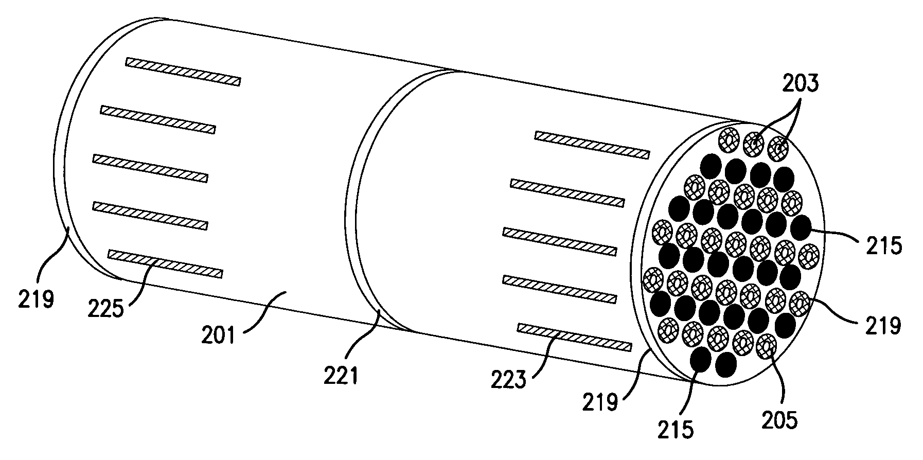
In one embodiment of the present invention, a series of cross-flow contactors is used to create a parallel channel contactor that has separate and parallel adsorption and heating channels. In this embodiment, individual segments of a cross-flow contactor are stacked or arranged so that the average flow of fluid during regeneration is counter-current or co-current to the average direction of flow of flue gas during the adsorption step. One way to construct a cross-flow contactor is to coat one set of channels of a cross-flow heat exchanger with an adsorbent. Cross-flow exchangers are convenient configurations for use with the present invention because their compact configuration is achieved via high heat transfer coefficients. However, when heat and mass transfer is engineered to give temperature gradients in one set of channels and concentration gradients in the other, a single cross-flow exchanger would have some adsorption paths heat up (or cool down) earlier than others. This wou...

example 3

This example illustrates use of a parallel contactor in a separation that removes CO2 from flue gas in a thermal swing adsorption process. Flue gas or stack gas is emitted in a wide variety of industrial processes. Pressure of the flue gas is typically slightly above atmospheric pressure and is generally less than two atmospheres. The temperature of the flue gas is typically in a range from about 150° C. to about 250° C. The major components in the gas are typically N2, O2, CO2, and H2O, Small quantities of pollutants such as NOx and SOx are often present. CO2 concentration in the gas is usually in a range from 3 mol % to 15 mol % and H2O in the gas is usually in a range from 0.1 mol % to 15 mol %. The total molar concentration of CO2+H2O is usually less than about 25 mol % when a stoichiometric combustion produces the stack gas and is usually less than about 15 mol % when dilution or excess air is employed in the process to limit the temperature in the higher temperature portion of...


PUM

PropertyMeasurementUnit
temperatureaaaaaaaaaa
angleaaaaaaaaaa
temperatureaaaaaaaaaa

Abstract

The separation of a target gas from a mixture of gases using a thermal swing adsorption process wherein a thermal wave is used, primarily in the desorption step. The process of this invention enables one to separately remove multiple contaminants from a treated gaseous stream.

Description

FIELD OF THE INVENTIONThe present invention relates to the separation of a target gas from a mixture of gases using a thermal swing adsorption process wherein a thermal wave is developed and utilized, primarily in the desorption step. The process of this invention enables one to separately remove multiple contaminants from a treated gaseous stream via utilizing a single adsorbent contactor to produce multiple product streams.BACKGROUND OF THE INVENTIONGas separation is important in various industries, particularly in the production of fuels, chemicals, petrochemicals and specialty products. A gas separation can be accomplished by a variety of methods that, assisted by heat, solids, or other means, generally exploits the differences in physical and / or chemical properties of the components to be separated. For example, gas separation can be achieved by partial liquefaction or by utilizing a solid adsorbent material that preferentially retains or adsorbs a more readily adsorbed compone...

Claims


Application Information

Patent Timeline
Patent Type & Authority Patents(United States)
IPC IPC(8): B01D53/04
CPCB01D53/02B01D53/0423B01D53/0462C10L3/10C10L3/102B01D2253/108B01D2253/308B01D2253/311Y02C10/08B01D2256/10B01D2257/102B01D2257/304B01D2257/504B01D2253/342Y02C20/40
Inventor HERSHKOWITZ, FRANKDECKMAN, HARRY W.NORTHROP, PAUL S.KELLEY, BRUCE T.
Owner EXXON RES & ENG CO
Why Eureka
Try Eureka