Control of particles on semiconductor wafers when implanting boron hydrides

Active Publication Date: 2009-12-03
AXCELIS TECHNOLOGIES
View PDF9 Cites 36 Cited by
  • Summary
  • Abstract
  • Description
  • Claims
  • Application Information

AI Technical Summary

Benefits of technology

[0016]The present invention overcomes the limitations of the prior art by providing a method for reducing particle contamination in a molecular ion implantation system, wherein contamination is not necessarily removed from the ion implantation system, but rather, transformed. Consequently, the following presents a simplified summary of the invention in order to provide a basic understanding of some aspects of the invention. This summary is not an extensive overview of the invention. It is intended to neither identify key or critical elements of the invention nor delineate the scope of the invention. Its purpose is to present some concepts of the invention in a simplified form as a prelude to the more detailed description that is presented later.
[0017]The present invention is directed generally toward an apparatus and method for reducing particle contamination in an ion implantation system using a gas for transforming contamination in the ion implantation system. The method comprises providing an ion implantation system for implanting ions into one or more workpieces via an ion beam, such as a molecular ion beam. The ion beam, for example, comprises a boron hydride such as decaborane or octadecaborane. The ion implantation system, for example, comprises one or more components under selective vacuum, wherein the one or more components have one or more contaminants

Problems solved by technology

In low energy applications, however, the beam of boron ions will suffer from a condition known as “beam blow-up”, which refers to the tendency for like-charged ions within the ion beam to mutually repel each other.
This severely reduces beam transmission as beam energy is reduced.
Implementations of decaborane ion sources, however, have led to unique particle contamination issues, as dissociation of the decaborane molecule and fragmentation of the B10HX+desired parent ion can occur, and substantially large particles can quickly accumulate on various components 34 and surfaces 38 within the ion implantation system 10.
Manual cleaning is typically costly, not only in terms of time and la

Method used


Image

  • Control of particles on semiconductor wafers when implanting boron hydrides
  • Control of particles on semiconductor wafers when implanting boron hydrides
  • Control of particles on semiconductor wafers when implanting boron hydrides

Examples


Embodiment Construction

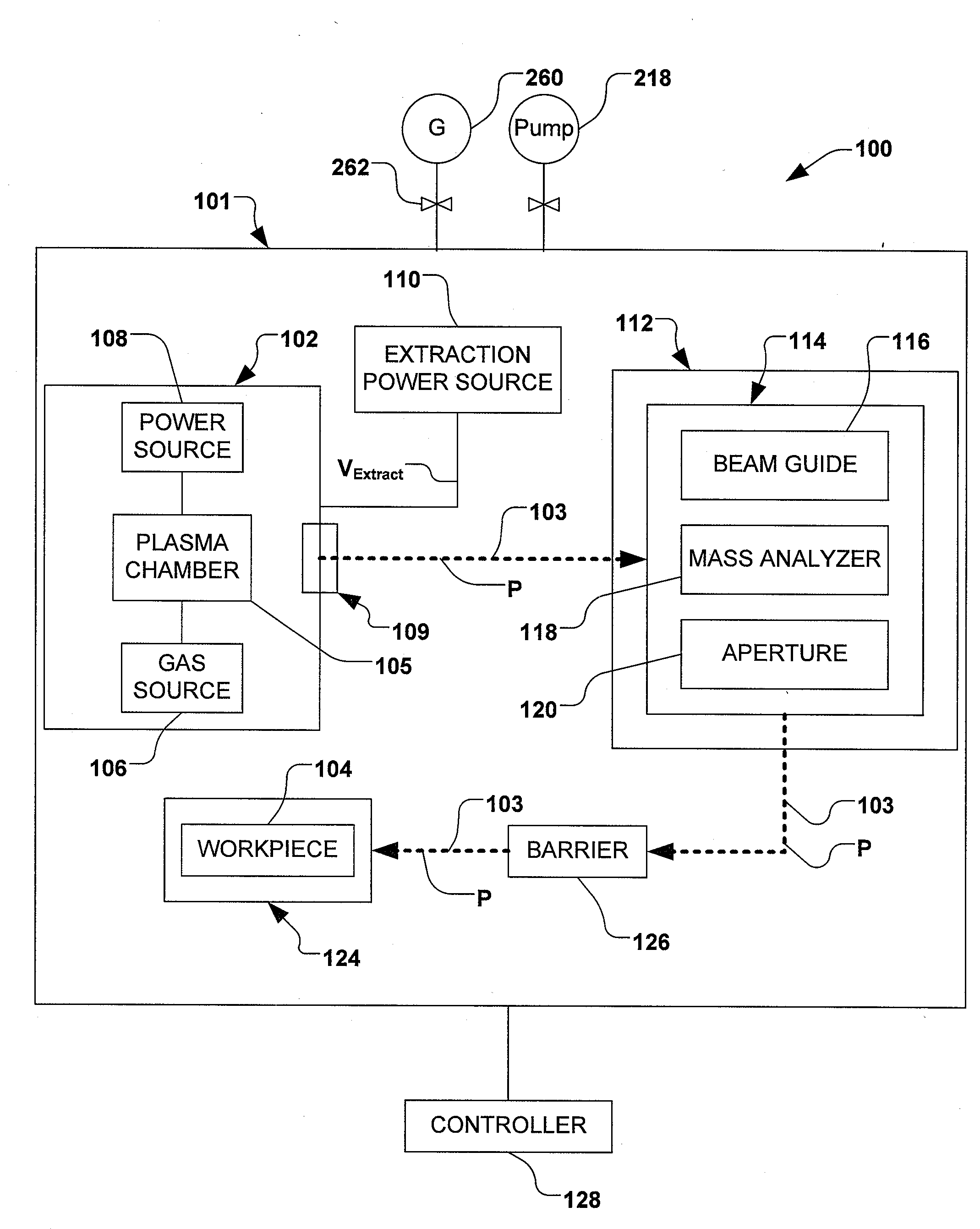
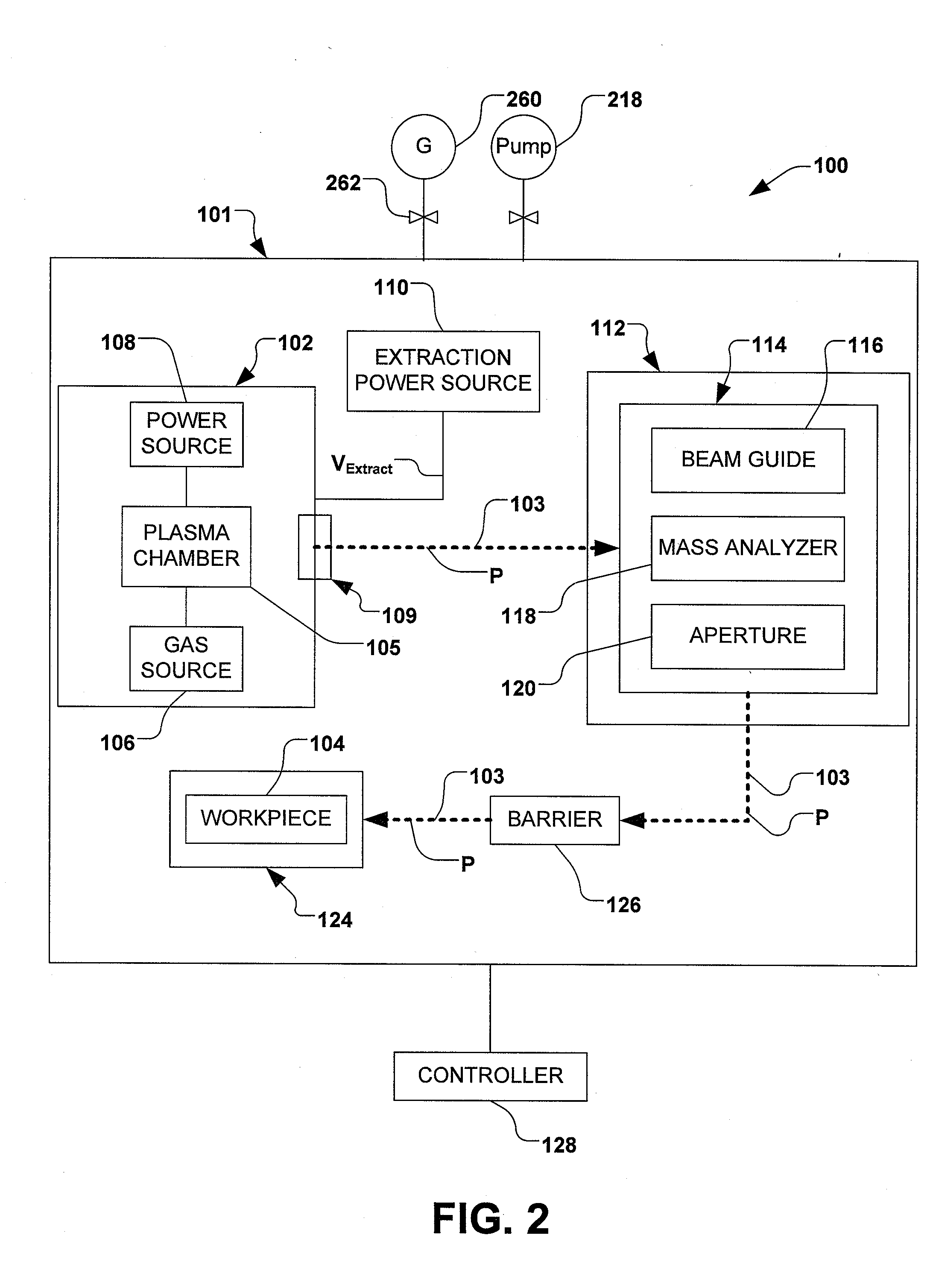
[0026]The present invention is directed generally towards a method and apparatus for reducing particle contamination during an implantation of ions into one or more workpieces. More particularly, the method provides an introduction of a non-etchant gas containing water vapor to an ion implantation system capable of generating ions form boron hydride chemistries, wherein contaminants are generally transformed, rather than removed, from the ion implantation system. Accordingly, the present invention will now be described with reference to the drawings, wherein like reference numerals are used to refer to like elements throughout. It should be understood that the description of these aspects are merely illustrative and that they should not be taken in a limiting sense. In the following description, for purposes of explanation, numerous specific details are set forth in order to provide a thorough understanding of the present invention. It will be evident to one skilled in the art, howe...


PUM


Abstract

A method for reducing particle contamination during implantation of ions comprises providing an implantation system for implanting ions into a workpiece via an ion beam, wherein one or more components are under selective vacuum and have one or more contaminants in a first state disposed thereon. A gas is introduced to the implantation system, wherein the gas generally reacts with at least a portion of the one or more contaminants, therein transforming the at least a portion of the one or more contaminants into a second state The at least a portion of the one or more contaminants in the second state remain disposed on the one or more components, and wherein the at least a portion of the second state of the one or more contaminants generally does not produce particle contamination on the one or more workpieces.

Description

REFERENCE TO RELATED APPLICATION[0001]This application claims priority to and the benefit of U.S. Provisional Application Ser. No. 61 / 057,485 which was filed May 30, 2008, entitled, CONTROL OF PARTICLES ON SEMICONDUCTOR WAFERS WHEN IMPLANTING BORON HYDRIDES, the entirety of which is hereby incorporated by reference as if fully set forth herein.FIELD OF THE INVENTION[0002]The present invention relates generally to ion implantation systems, and more specifically to systems and methods controlling particulate contamination in an ion implantation system.BACKGROUND OF THE INVENTION[0003]In the manufacture of semiconductor devices and other products, ion implantation systems are used to impart impurities, known as dopant elements, into semiconductor wafers, display panels, or other workpieces. Conventional ion implantation systems or ion implanters treat a workpiece with an ion beam in order to produce n- or p-type doped regions, or to form passivation layers in the workpiece. When used f...

Claims


Application Information

Patent Timeline
IPC IPC(8): H01J37/08
CPCH01J2237/022H01J37/3171
Inventor RAY, ANDREW M.
Owner AXCELIS TECHNOLOGIES
Why Eureka
Try Eureka