
Combined removal method for contaminants from coal-fired flue gas and special purification reactor thereof

A combined removal and coal-fired flue gas technology, applied in separation methods, chemical instruments and methods, and separation of dispersed particles, to achieve the effects of eliminating adverse effects, low cost, and compact structure

Inactive Publication Date: 2009-10-28
HUAZHONG UNIV OF SCI & TECH
View PDF4 Cites 36 Cited by
  • Summary
  • Abstract
  • Description
  • Claims
  • Application Information

AI Technical Summary

Problems solved by technology

[0011] The purpose of the present invention is to overcome the deficiencies of the existing coal-fired flue gas pollutant control technology, and provide a joint removal method for coal-fired flue gas pollutants, which can effectively realize the sulfur oxides, The combined removal of nitrogen oxides, highly toxic mercury and their compounds, even including volatile organic compounds, can also recover the by-products produced in the pollutant removal process and realize resource utilization; the invention also provides the method A special purification reactor is used, which has the advantages of uniform and firm filling of activated carbon fibers, small flow resistance of flue gas, and high efficiency of pollutant adsorption and removal.

Method used


Image

  • Combined removal method for contaminants from coal-fired flue gas and special purification reactor thereof
  • Combined removal method for contaminants from coal-fired flue gas and special purification reactor thereof
  • Combined removal method for contaminants from coal-fired flue gas and special purification reactor thereof

Examples


Embodiment 1

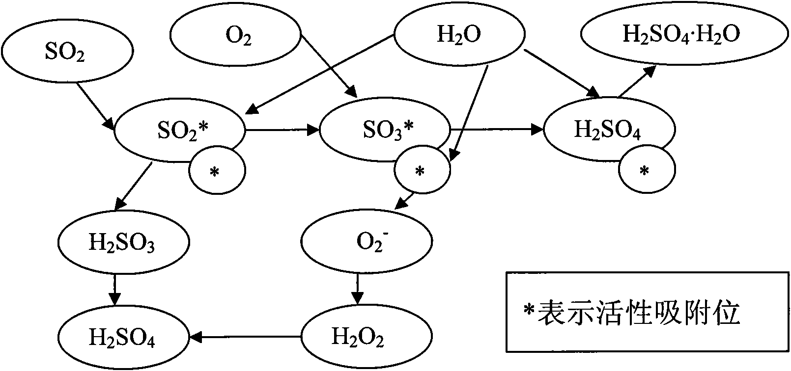
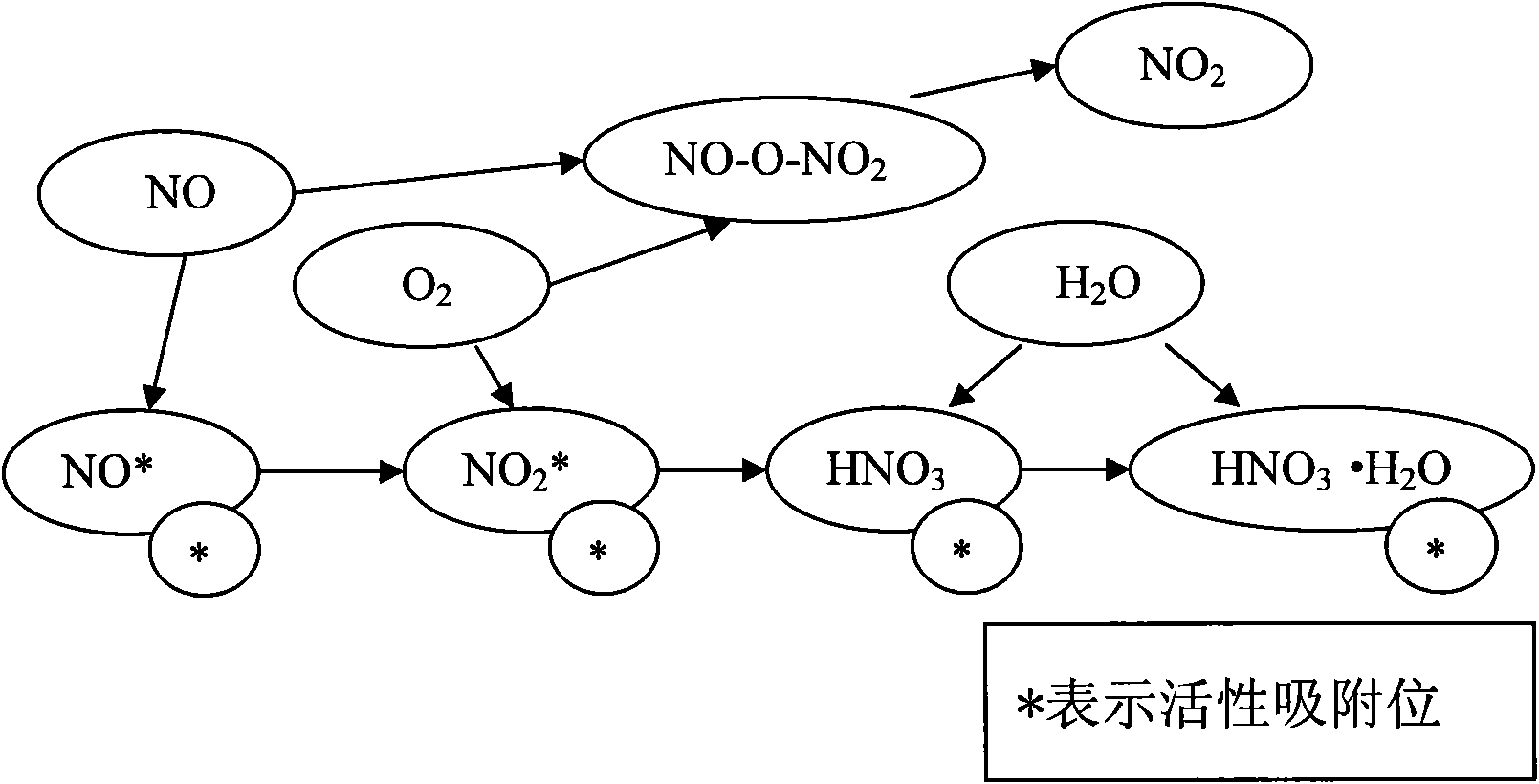
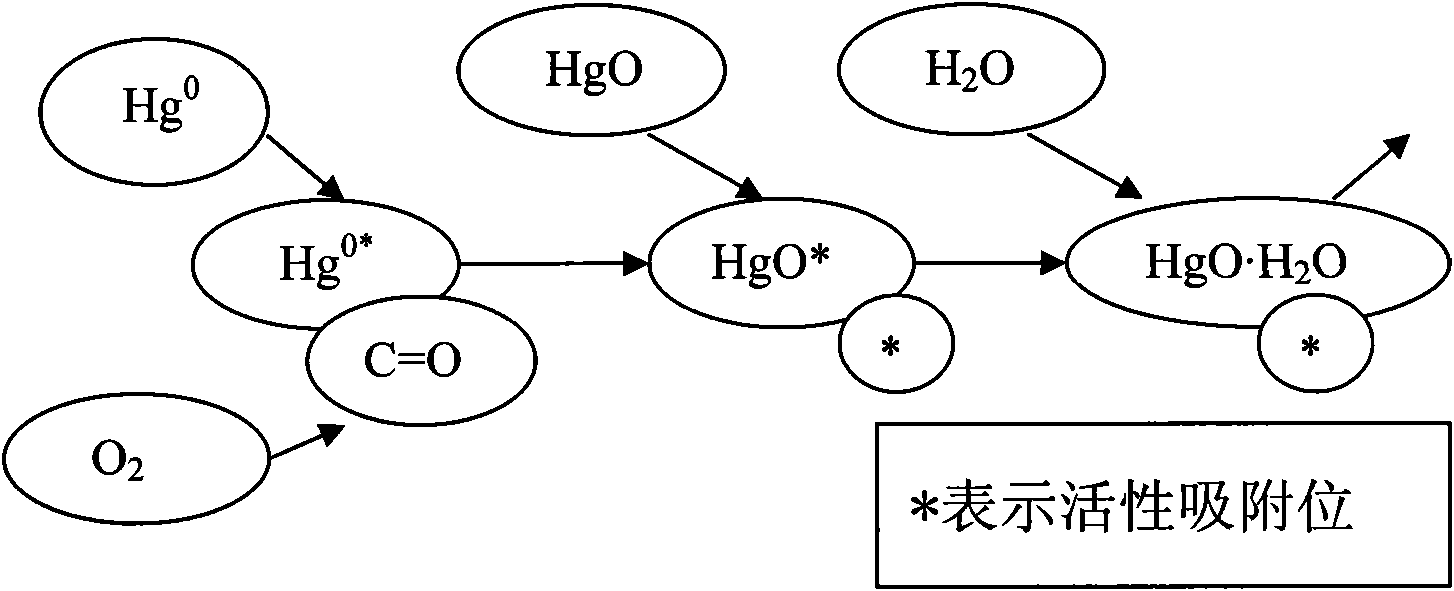
[0050]The flue gas at the tail of the coal-fired boiler after high-efficiency dust removal is cooled to 145°C through a heat exchanger, and then passed into the first-stage purification reactor loaded with modified activated carbon fibers, and the gas supply volume of the steam generator and the reactor are adjusted. The injection amount of atomized water in the reactor is kept at 90°C, the volume content of water vapor in the flue gas is 12%, the volume content of oxygen in the flue gas is 10%, and the sulfur dioxide and Sulfur trioxide, elemental mercury and its compounds, volatile organic pollutants in flue gas are oxidized and decomposed into carbon dioxide and water, and other heavy metals are dissolved in SO 2 In the sulfuric acid droplets formed after oxidation.

[0051] The flue gas discharged from the first-stage purification reactor is introduced into the second-stage purification reactor loaded with modified activated carbon fibers through the pipeline, and the in-l...

Embodiment 2

[0056] The flue gas at the tail of the coal-fired boiler after high-efficiency dust removal is cooled to 120°C through a heat exchanger, and then passed into the first-stage purification reactor loaded with modified activated carbon fibers to adjust the gas supply of the steam generator and the reactor The injection amount of atomized water in the reactor is kept at 55°C, the volume content of water vapor in the flue gas is 8%, the volume content of oxygen in the flue gas is 7%, and the sulfur dioxide and sulfur dioxide in the flue gas are removed. Sulfur trioxide, elemental mercury and its compounds, volatile organic pollutants in flue gas are oxidized and decomposed into carbon dioxide and water, and other heavy metals are dissolved in SO 2 In the sulfuric acid droplets formed after oxidation.

[0057] The flue gas discharged from the first-stage purification reactor is introduced into the second-stage purification reactor loaded with modified activated carbon fibers through...

Embodiment 3

[0062] The flue gas at the tail of the coal-fired boiler after high-efficiency dust removal is cooled to 80°C through a heat exchanger, and then passed into the first-stage purification reactor loaded with modified activated carbon fibers to adjust the gas supply of the steam generator and the reactor The injection amount of atomized water in the reactor is kept at 30°C, the volume content of water vapor in the flue gas is 6%, the volume content of oxygen in the flue gas is 5%, and the sulfur dioxide and Sulfur trioxide, elemental mercury and its compounds, volatile organic pollutants in flue gas are oxidized and decomposed into carbon dioxide and water, and other heavy metals are dissolved in SO 2 In the sulfuric acid droplets formed after oxidation.

[0063] The flue gas discharged from the first-stage purification reactor is introduced into the second-stage purification reactor loaded with modified activated carbon fibers through the pipeline, and the in-line heater arrange...


PUM

PropertyMeasurementUnit
Specific surface areaaaaaaaaaaa
Gap widthaaaaaaaaaa
Specific areaaaaaaaaaaa

Abstract

The invention discloses a combined removal method for contaminants from a coal-fired flue gas and a special purification reactor thereof. The method comprises the following steps: (1) the flue gas to which dust removal is conducted at the tail part of a coal-fired boiler is cooled down by a heat exchanger; (2) the cooled flue gas passes through a primary purification reactor and a secondary purification reactor successively; (3) the flue gas discharged by step 2 is heated up by the heat exchanger and then discharged into atmosphere; (4) online monitoring is conducted to the flue gas discharged by step 3; when the emission concentration of the contaminants is higher than the emission standard, step 5 is conducted; otherwise, step 1 to step 3 are conducted circularly; (5) water is sprayed into the primary purification reactor and the secondary purification reactor to repeatedly wash the removal product attached to the surface of activated carbon fiber; and (6) air is heated up and then input into the primary purification reactor and the secondary purification reactor which are washed with water in step 5 so as to dry the activated carbon fiber in the reactors and then step 1 is conducted. The invention has the advantages of high removal rate for a plurality of contaminants, simple technique flow, integrated removal device, recyclable byproducts and the like.

Description

technical field [0001] The invention belongs to the technical field of environmental protection, and relates to a method for simultaneously removing various pollutants in coal-fired flue gas, including sulfur oxides, nitrogen oxides, trace highly toxic element mercury and its compounds, and volatile organic pollutants. The special-purpose purification reactor particularly relates to a waste gas purification method using activated carbon fiber as an adsorption material. Background technique [0002] In addition to producing a large amount of sulfur oxides (SOx) and nitrogen oxides (NOx), coal combustion also releases mercury and organic pollutants, which have caused great harm to the atmospheric environment and human health; especially mercury emissions, due to toxicity Large and extremely volatile and difficult to control, it has become an important environmental problem in our country. [0003] In recent years, my country has independently developed and introduced many pol...

Claims


Application Information

Patent Timeline
IPC IPC(8): B01D53/75B01D53/04B01D53/86B01D53/50B01D53/56B01D53/64
Inventor 邱建荣刘豪刘子红曾汉才赵然闫志强谭增强
Owner HUAZHONG UNIV OF SCI & TECH
Learn More