Cementitious grout and methods of using same

a cementitious grout and cement technology, applied in the direction of geothermal energy generation, chemistry apparatus and processes, light and heating apparatus, etc., can solve the problems of almost a maximum oxidation impairment, adverse effects on heat transfer rate, aluminum mixing poorly with cement, etc., and achieve good geothermal electrical transfer and good geothermal heat transfer

Inactive Publication Date: 2011-05-10
WIGGS B RYLAND
View PDF5 Cites 24 Cited by
  • Summary
  • Abstract
  • Description
  • Claims
  • Application Information

AI Technical Summary

Benefits of technology

[0033]FIG. 1 is a side view of a geothermal heat pump system U loop within a well / hole / borehole. After the U loop has been inserted, the remaining empty void space within the hole has been filled with a heat conductive cementitious grout, preferably such as Grout 111MG, to effect good geothermal heat transfer with the adjacent and surrounding earth.
[0034]FIG. 2 is a side view of a metal grounding rod within a well / hole / borehole. After the metal grounding rod has been inserted, the remaining empty void space within the hole has been filled with an electrically conductive cementitious grout, preferably such as Grout 111MG, to effect good geothermal electrical transfer with the adjacent and surrounding earth.

Problems solved by technology

However, it is important to note that the thermally conductive grout mixture taught by Buchi is not for geothermal heating / cooling applications, and is not for the purpose of enhancing the sub-surface heat exchange line in a geothermal heat pump system application.
Buchi' design is never intended for the earth to act as a heat sink, as would be the case in a reverse-cycle geothermal heat pump system, and is not intended for applications less than 1,500 meters deep (typically geothermal heat pump systems operate at depths down to about 300 feet deep).
Further, while Buchi teaches the use of water and cement mixed with a preferable silver, copper, or aluminum powder, Buchi overlooks the facts that the surface of silver and copper quickly oxidize, which oxidized surface inhibits heat transfer, that a powdered metal will result in almost a maximum oxidation impairment, and that aluminum does not mix well with cement.
Such common clay-based grouts without cement typically attain heat transfer rates of only 0.69 to 1.2 Btu / hr. ft. degree F., with the heat transfer rate being adversely affected as the grout is dried out via heat pump system operation in the cooling mode.
Dried, clay-based, grouts tend to significantly loose heat transfer abilities and also tend to shrink and pull away from sub-surface geothermal heat transfer tubing, leaving non-heat conductive void areas.
However, this lack of pH level restriction, in a DX system application, could be catastrophic, resulting in sub-surface refrigerant transport tubing deterioration and leaks, as sulfur water, water with a pH level below 5.5, and water with a pH level above 11, and the like, can be corrosive to copper.

Method used


Image

  • Cementitious grout and methods of using same
  • Cementitious grout and methods of using same
  • Cementitious grout and methods of using same

Examples


Embodiment Construction

[0038]The following detailed description is of the best presently contemplated mode of carrying out the invention. The description is not intended in a limiting sense, and is made solely for the purpose of illustrating the general principles of the invention. The drawings are not necessarily drawn to scale. The various features and advantages of the present invention may be more readily understood with reference to the following detailed description taken in conjunction with the accompanying drawings.

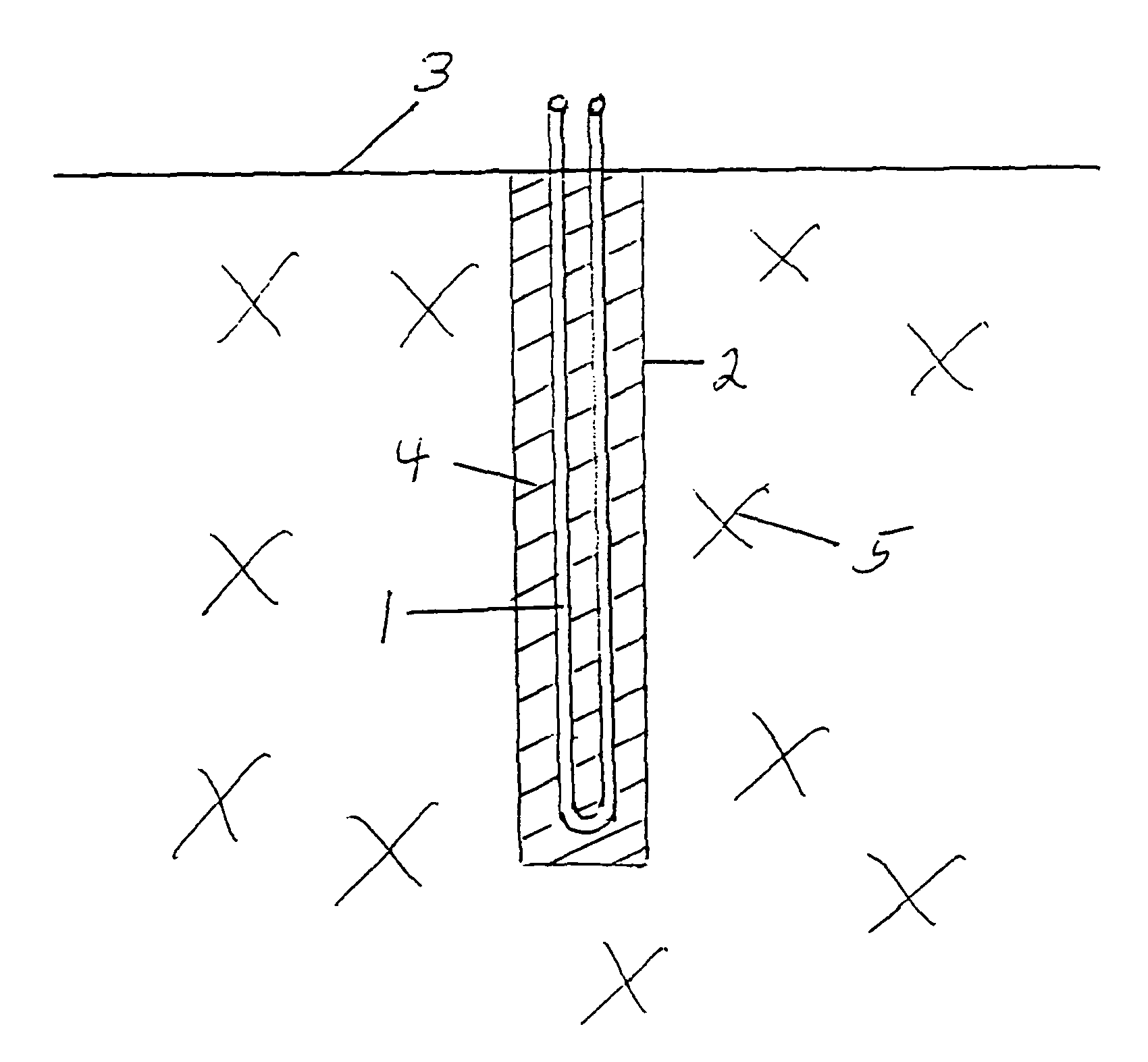
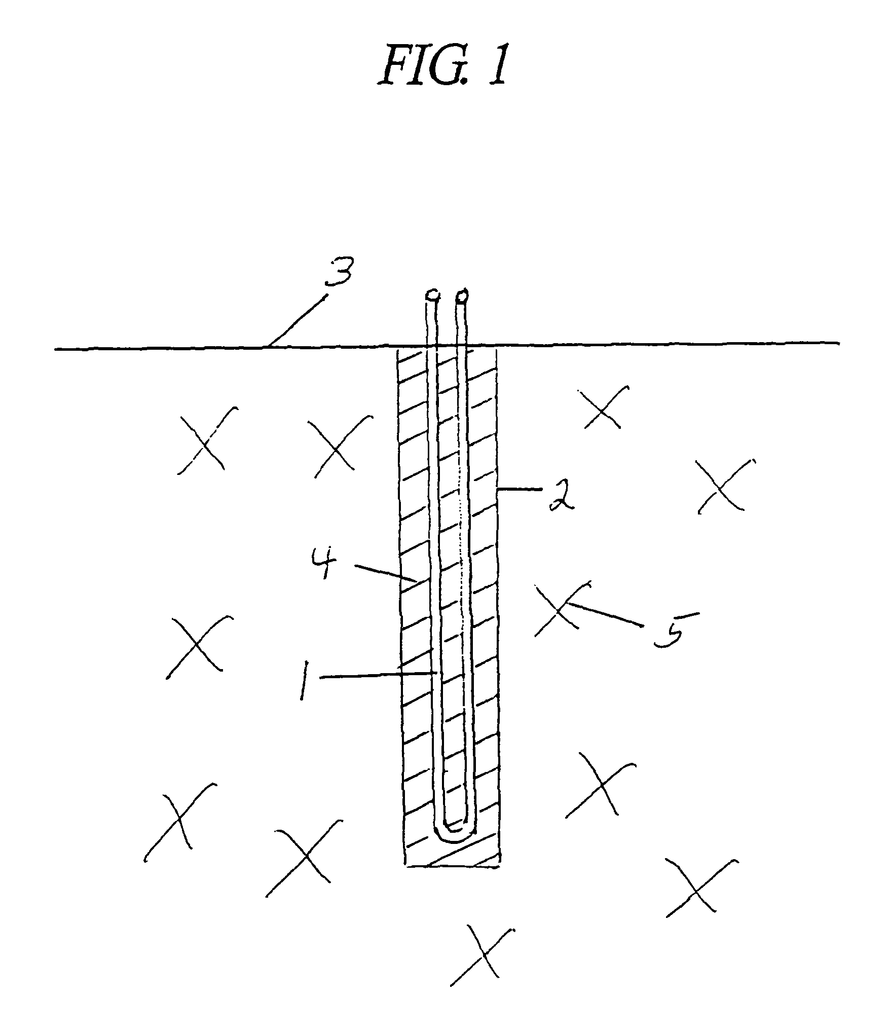
[0039]Referring now to the drawings in detail, where like numerals refer to like parts or elements, there is shown in FIG. 1 a side view of a U loop 1 within a well / hole / borehole 2. The U loop 1 is comprised of at least one of a plastic tubing / piping (typically used with water-source heat pump systems, which systems are well understood by those skilled in the art) and a metal tubing / piping (typically used in conjunction with DX heat pump systems, which systems are well understood by tho...


PUM

PropertyMeasurementUnit
particle sizeaaaaaaaaaa
pHaaaaaaaaaa
depthsaaaaaaaaaa

Abstract

A cementitious Grout 111MG, with improved thermal and electrical conductivity over Grout 111, for use in at least one of geothermal heat pump systems and metal electrical grounding rod systems, with improved conductivity achieved by means of substituting metal grit for sand, a cementitious grout where both Grout 111MG and Grout 111 have mix water pH level limitations so as not to be corrosive to metals, a new use for Grout 111 as a fill material surrounding electrical grounding rods for enhanced electrical conductivity over traditional grouts, and a new use where both Grout 111MG and Grout 111 may be utilized to surround at least one of geothermal heat pump sub-surface heat transfer fluid conductive tubing/piping and electrical grounding rods installed within at least one of a well/borehole, a trench, and a pit.

Description

CROSS-REFERENCES TO RELATED APPLICATIONS[0001]This application is a Non-Provisional Utility application which claims benefit of co-pending U.S. Patent Application Ser. No. 60 / 656,967 filed Feb. 28, 2005, entitled “Grout 111MG and Methods of Using Same” which is hereby incorporated by reference.[0002]A portion of the disclosure of this patent document contains material that is subject to copyright protection. The copyright owner has no objection to the facsimile reproduction by anyone of the patent document or the patent disclosure, as it appears in the Patent and Trademark Office patent file or records, but otherwise reserves all copyright rights whatsoever.STATEMENT REGARDING FEDERALLY SPONSORED RESEARCH OR DEVELOPMENT[0003]Not ApplicableREFERENCE TO SEQUENCE LISTING OR COMPUTER PROGRAM LISTING APPENDIX[0004]Not ApplicableBACKGROUND OF THE INVENTION[0005]The present invention relates to an improved sub-surface grouting material for use as at least one of a thermally conductive fill...

Claims


Application Information

Patent Timeline
Patent Type & Authority Patents(United States)
IPC IPC(8): C04B14/06C04B14/34
CPCC04B28/02C09K8/467E02D3/12C04B14/06C04B14/34C04B20/008C04B22/002C04B2111/72F24J3/083Y02E10/125C04B2103/32F24T10/10F24T10/15Y02E10/10
Inventor WIGGS, B. RYLAND
Owner WIGGS B RYLAND
Why Eureka
Try Eureka