Passive background correction method for spatially resolved detection

a background correction and spatial resolution technology, applied in the direction of optical radiation measurement, distance measurement, instruments, etc., can solve the problems of increasing the uncertainty of the magnitude of the actual signal, the increase of the intensity of passive lighting sources,

Active Publication Date: 2011-05-10
NAT TECH & ENG SOLUTIONS OF SANDIA LLC
View PDF9 Cites 22 Cited by
  • Summary
  • Abstract
  • Description
  • Claims
  • Application Information

AI Technical Summary

Problems solved by technology

One significant problem with interleaving the passive background data acquisition with the acquisition of spectra from the desired target is that the intensity of passive lighting sources often changes even on the short timescale typically found between laser pulses.
This leads to increased uncertainty in the magnitude of the actual signal that may be originating from the target of interest.

Method used


Image

  • Passive background correction method for spatially resolved detection
  • Passive background correction method for spatially resolved detection
  • Passive background correction method for spatially resolved detection

Examples


Embodiment Construction

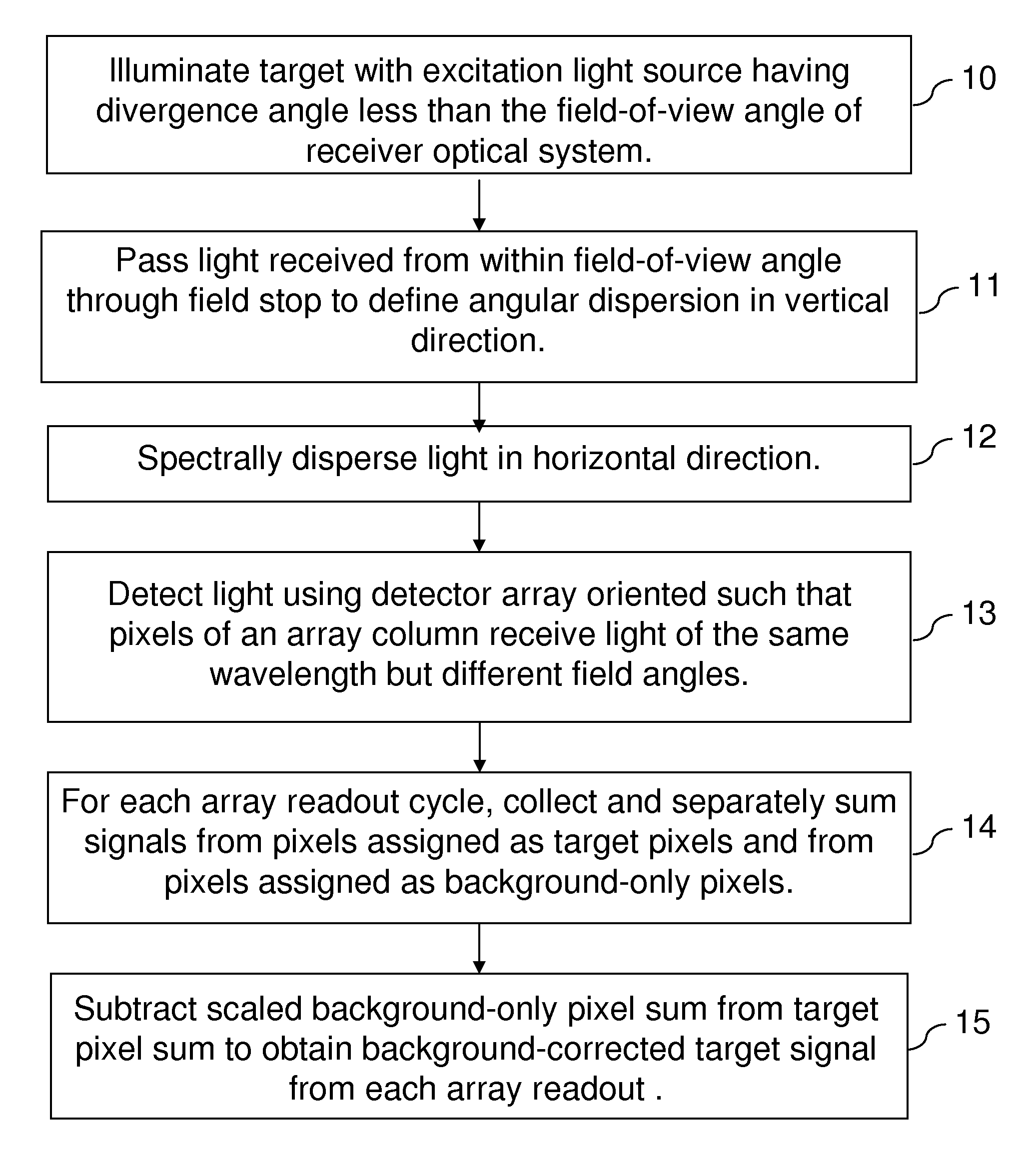
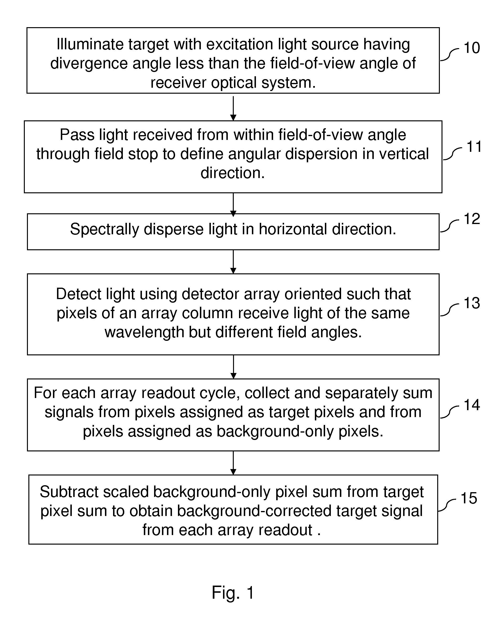
[0017]This invention comprises a method for passive background correction during spatially or angularly resolved detection of emission that is based on the simultaneous acquisition of both the passive background spectrum and the spectrum of the target of interest. For purposes of the description of embodiments of the invention, the term simultaneous refers to events and actions occurring within approximately the time corresponding to a readout cycle of a pixelated detector array or to a round-trip transit time of a single laser pulse to a remote target and back to the receiver optical system. For the purposes of description, the terms laser light, laser beam, and laser pulse are employed for convenience, but it is to be understood that other collimated light sources with beam divergence angles less than the field-of-view angle of the receiver optical system may also be used. For the purposes of this invention, a target can comprise a solid, a liquid, or a gas; it can comprise a pure...


PUM


Abstract

A method for passive background correction during spatially or angularly resolved detection of emission that is based on the simultaneous acquisition of both the passive background spectrum and the spectrum of the target of interest.

Description

[0001]The United States Government has rights in this invention pursuant to Department of Energy Contract No. DE-AC04-94AL85000 with Sandia Corporation.BACKGROUND OF THE INVENTION[0002]This invention relates to a method for improved passive background subtraction using spatially resolved detection systems.[0003]Active remote sensing systems transmit a photoexcitation light pulse such as a laser pulse through the atmosphere, collect backscattered and fluorescent emission generated by interaction of the photoexcitation light with a target, and spectrally and temporally resolve the collected light. Computer algorithms are used to process the collected spectral data to discriminate between species of interest, interfering species, and passive background spectra. Often the spectral signal from a species of interest is relatively weak. Proper detection then requires accurate subtraction of passive background light contributions to the measured spectra. Passive background light is light fr...

Claims


Application Information

Patent Timeline
Patent Type & Authority Patents(United States)
IPC IPC(8): G01C3/08
CPCG01J3/02G01J3/0208G01J3/027G01J3/28G01J3/2823G01J3/44G01S17/89G01N21/65G01S7/48G01S7/4811G01N21/6402G01N2021/1793G01N2021/4709
Inventor SCHMITT, RANDAL L.HARGIS, JR., PHILIP J.
Owner NAT TECH & ENG SOLUTIONS OF SANDIA LLC
Why Eureka
Try Eureka