Multiple output switching power source apparatus including multiple series resonant circuits

a power source apparatus and multi-output technology, applied in the direction of electric variable regulation, process and machine control, instruments, etc., can solve the problems of deteriorating cross regulation, proportional change in other outputs, and the inability to directly take a plurality of outputs from windings, etc., to achieve the effect of increasing cost and packaging space, and complicating structur

Active Publication Date: 2011-05-17
SANKEN ELECTRIC CO LTD
View PDF20 Cites 15 Cited by
  • Summary
  • Abstract
  • Description
  • Claims
  • Application Information

AI Technical Summary

Benefits of technology

[0017]FIG. 3 is a circuit diagram illustrating the configuration of a multiple output switching power source apparatus according to another related art. This multiple output switching power source apparatus employs, instead of the second rectifying-smoothing circuit illustrated in FIG. 1, a regulator 12 such as a dropper and a step-down chopper. The regulator 12 is used to generate a second output voltage Vo2 from a first output voltage Vo1 so that the outputs are stabilized. This multiple output switching power source apparatus can solve the cross regulation problem related to two outputs. However, the regulator 12 increases a loss, the additional parts including switching elements, choke coils, control ICs, and the like increase the cost and a packaging space, and the switching regulator such as a step-down chopper causes noise.
[0020]The present invention can provide a multiple output switching power source apparatus capable of stabilizing a plurality of outputs even if there are load variations.

Problems solved by technology

As a result, a change in Vf due to a load variation at each output may deteriorate a cross regulation.
In the case of a power source apparatus that is designed to vary output voltages, changing one output voltage results in causing a proportional change in the other output.
Then, it will be impossible to directly take a plurality of outputs from windings.
However, the regulator 12 increases a loss, the additional parts including switching elements, choke coils, control ICs, and the like increase the cost and a packaging space, and the switching regulator such as a step-down chopper causes noise.
As mentioned above, the multiple output switching power source apparatuses according to the related arts have the problem of worsening a cross regulation due to load variations at each output and the problem of not directly taking a plurality of outputs from windings in the case of the power source designed to provide variable output voltages.
The technique of arranging a regulator on the secondary side to solve the problem of cross regulation worsens a loss due to the regulator, increases the cost and a packaging space due to additional parts, and causes noise due to the regulator.
The switching converter circuit disclosed in the above related art needs a plurality of secondary windings for a transformer, to thereby cause a problem of complicating the structure.

Method used


Image

  • Multiple output switching power source apparatus including multiple series resonant circuits
  • Multiple output switching power source apparatus including multiple series resonant circuits
  • Multiple output switching power source apparatus including multiple series resonant circuits

Examples


embodiment 1

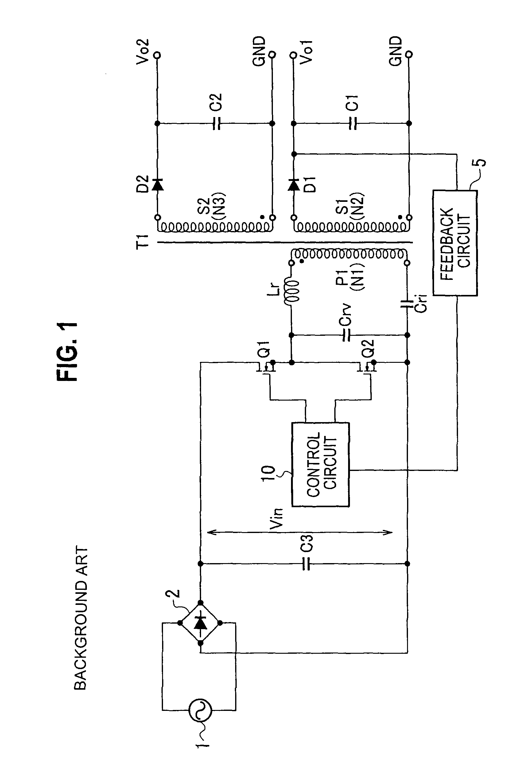
[0057]FIG. 4 is a circuit diagram illustrating the configuration of a multiple output switching power source apparatus according to the embodiment 1 of the present invention. In this multiple output switching power source apparatus, the primary side of a transformer T1 includes a full-wave rectifying circuit 2 to rectify an AC voltage from a commercial power source 1, a smoothing capacitor C3 connected between output terminals of the full-wave rectifying circuit 2, to smooth an output from the full-wave rectifying circuit 2, a first switching element Q1 and a second switching element Q2 that are connected in series between both ends of the smoothing capacitor C3, to receive a terminal voltage of the smoothing capacitor C3 as a DC input voltage Vin, a control circuit 10a to control ON / OFF of the first switching element Q1 and second switching element Q2, a voltage resonant capacitor Crv connected in parallel with the second switching element Q2, and a first series resonant circuit co...

embodiment 2

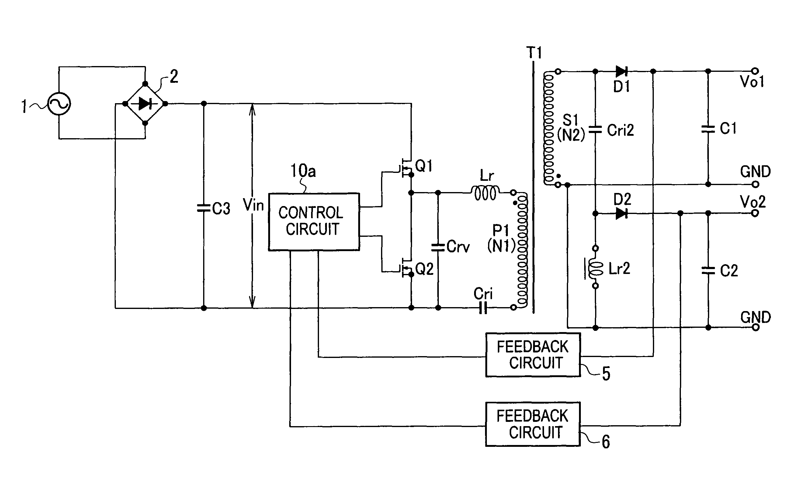
[0074]FIG. 6 is a circuit diagram illustrating the configuration of a multiple output switching power source apparatus according to the embodiment 2 of the present invention. This multiple output switching power source apparatus differs from that of the embodiment 1 in the configuration and operation of the secondary side of a transformer T1. In the following, parts that differ from those of the embodiment 1 will mainly be explained.

[0075]On the secondary side of the transformer T1, there are arranged a first rectifying-smoothing circuit connected to a secondary winding S1 (the number of turns of N2) that is wound to generate a voltage whose phase is opposite to the phase of a voltage of a primary winding P1 of the transformer T1, a second series resonant circuit connected in parallel with the secondary winding S1, and a second rectifying-smoothing circuit connected to the second series resonant circuit.

[0076]The first rectifying-smoothing circuit has a diode D1, a smoothing capacit...

embodiment 3

[0087]FIG. 8 is a circuit diagram illustrating the configuration of a multiple output switching power source apparatus according to the embodiment 3 of the present invention. This multiple output switching power source apparatus differs from that of the embodiment 1 in the configuration of the secondary side of a transformer. In the following, parts that differ from those of the embodiment 1 will mainly be explained.

[0088]The transformer T2 has a first secondary winding S1 (the number of turns of N2) that is wound to generate a voltage whose phase is opposite to the phase of a voltage of a primary winding P1 and a second secondary winding S2 (the number of turns of N3) that is wound to generate a voltage whose phase is opposite to the phase of the voltage of the primary winding P1. The first secondary winding S1 and second secondary winding S2 are wound into a tight coupling. On the secondary side of the transformer T2, there are arranged a first rectifying-smoothing circuit connect...


PUM


Abstract

A multiple output switching power source apparatus includes first and second switching elements Q1 and Q2, a first series resonant circuit connected in parallel with Q1 or Q2 and having a first current resonant capacitor and a primary winding of a transformer that are connected in series, a first rectifying-smoothing circuit to rectify and smooth a voltage generated by a secondary winding of the transformer, a second series resonant circuit connected in parallel with the secondary winding and having a second current resonant capacitor and a second resonant reactor that are connected in series, a second rectifying-smoothing circuit to rectify and smooth a voltage of the second series resonant circuit, and a control circuit to determine an ON period of Q1 according to a voltage obtained from one of the first and second rectifying-smoothing circuits, determine an ON period of Q2 according to a voltage obtained from the other of the first and second rectifying-smoothing circuits, and alternately turn on / off Q1 and Q2.

Description

TECHNICAL FIELD[0001]The present invention relates to a multiple output switching power source apparatus having a plurality of outputs.BACKGROUND TECHNOLOGY[0002]FIG. 1 is a circuit diagram illustrating the configuration of a resonant-type multiple output switching power source apparatus according to a related art. In this multiple output switching power source apparatus, the primary side of a transformer T1 includes a full-wave rectifying circuit 2 to rectify an AC voltage from a commercial power source 1, a smoothing capacitor C3 connected between output terminals of the full-wave rectifying circuit 2, to smooth an output from the full-wave rectifying circuit 2, a first switching element Q1 and a second switching element Q2 (for example, MOSFETs) that are connected in series between ends of the smoothing capacitor C3, to receive a terminal voltage of the smoothing capacitor C3 as a DC input voltage sin, a control circuit 10 to control ON / OFF of the first switching element Q1 and s...

Claims


Application Information

Patent Timeline
Patent Type & Authority Patents(United States)
IPC IPC(8): H02J3/14
CPCH02M3/33561Y02B70/1433Y02B70/10H02M3/28
Inventor KYONO, YOICHI
Owner SANKEN ELECTRIC CO LTD
Why Eureka
Try Eureka