
Process and device for the pyrolysis of feedstock

a feedstock and pyrolysis technology, applied in the direction of distillation gas withdrawal, combustible gas production, electrical equipment, etc., can solve the problems of inefficiency or high cost of currently available, unfavorable output/input (o/i) at this time, and cannot be overemphasized that pyrolysis reactors produce a very complex volatile brew whose detailed constituency is still beyond the predictive capability of today's scien

Inactive Publication Date: 2011-05-24
GREEN LIQUID & GAS TECH
View PDF19 Cites 76 Cited by
  • Summary
  • Abstract
  • Description
  • Claims
  • Application Information

AI Technical Summary

Benefits of technology

"The patent text describes improvements to a pyrolysis system for converting solid fuels to energy. These improvements are based on the analysis of natural fuels and the properties of their pyrolysis products. The text describes the Green Pyrolyzer Gassifier (GPG) and its improvements, which include a new gasifier design and a new method for feedstock blending. The technical effects of these improvements include improved energy conversion efficiency, reduced emissions of harmful byproducts, and improved waste management. The text also mentions relevant patents and publications related to the pyrolysis technology."

Problems solved by technology

However, after extensive experimentation with such systems it became clear that when using a pyrolysis gas fired motor generator to produce electricity, the output / input (O / I) is not favorable at this time.
This is largely due to the inefficiency or high cost of currently available small scale gas to electricity converters.
Unfortunately the HHV of its gaseous product is not only energetically reduced by the air's 20% oxygen but even further reduced by dilution with air's 80% non-energetic nitrogen so that the product is a low HHV producer gas.
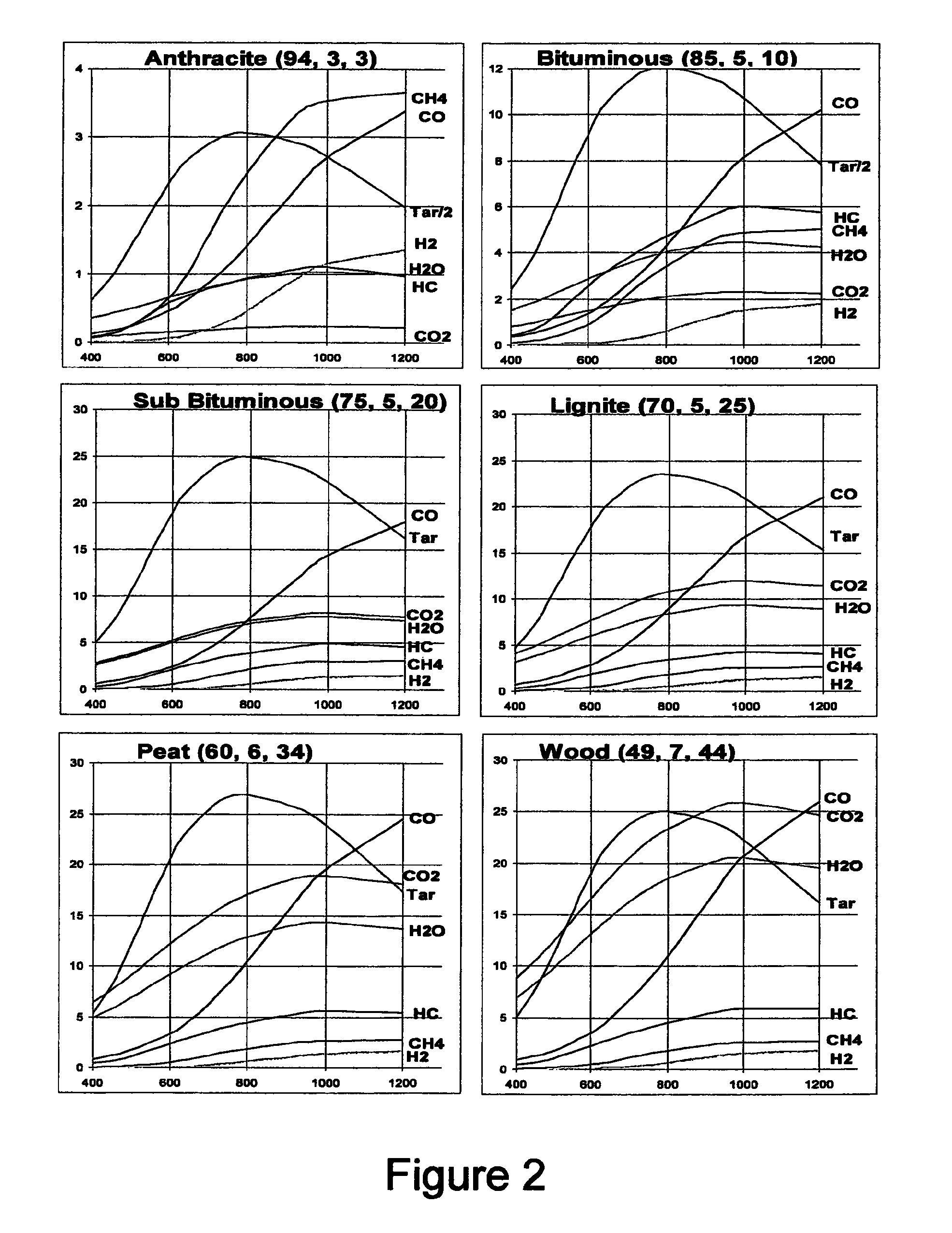
It cannot be over emphasized that pyrolytic reactors produce a very complex volatile brew whose detailed constituency is still beyond the predictive capability of today's science.

Method used


Image

  • Process and device for the pyrolysis of feedstock
  • Process and device for the pyrolysis of feedstock
  • Process and device for the pyrolysis of feedstock

Examples


Embodiment Construction

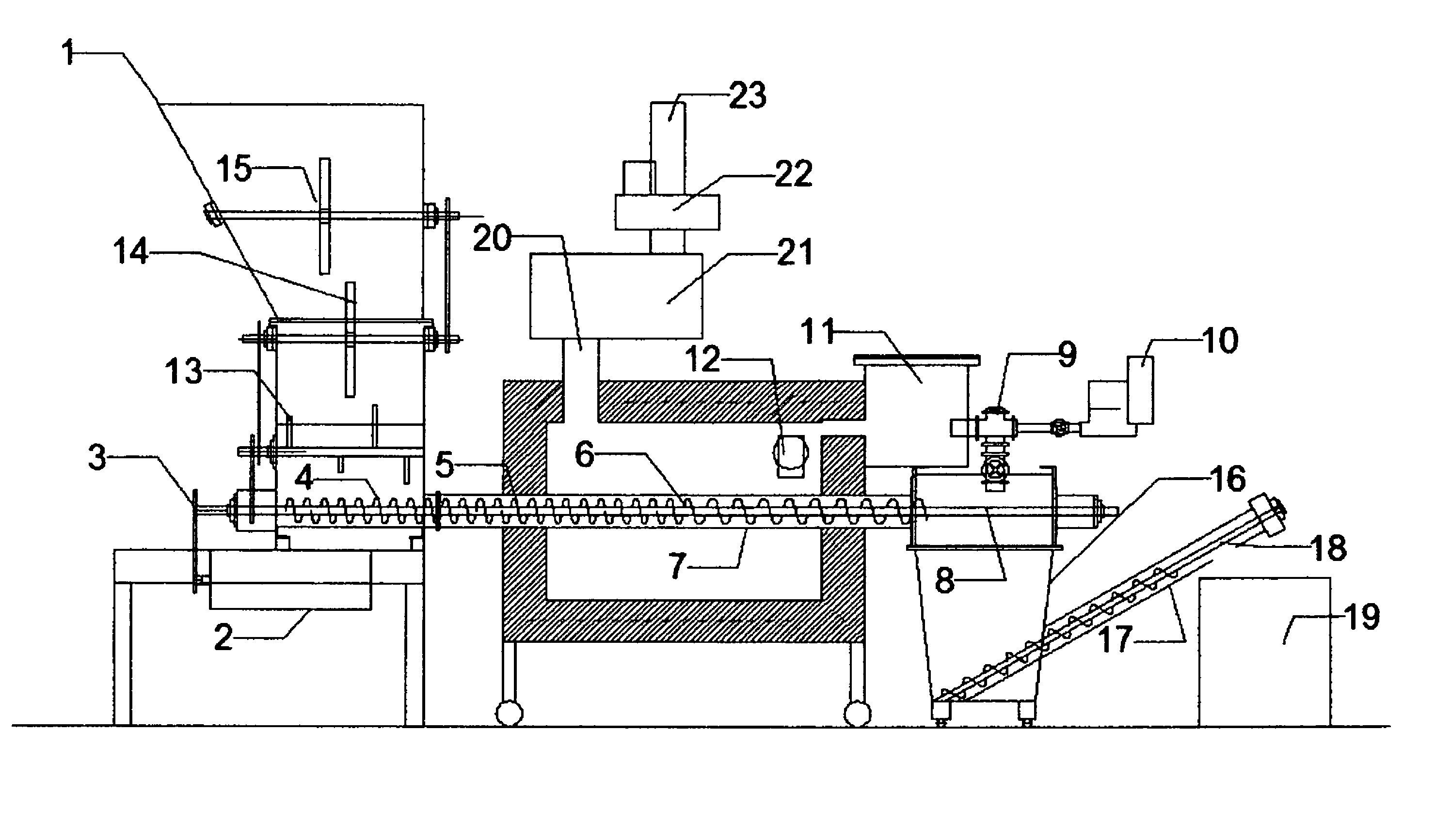
[0062]FIG. 4 shows a form of the GPG consisting of four major components[0063]1. a hopper system to accept and store feedstock input and help block air from entering the system and pyro-gas from leaking out.[0064]2. an auger reactor system to accept feedstock from the hopper, transport it to the oven where it is heated to high temperatures to form volatiles and char. FIG. 4 is a GPG form intended for mobile applications. Here the flow of feedstock is downward in the feed hopper, horizontal in the reactor, and then downward as char in the char receptor. Material flows, as illustrated in patents 374 and 597, are all downward but in the embodiment shown in FIG. 4, the reactor is horizontal to lower the height of the machine, which does not change the essential GPG pyrolysis processes.[0065]3. a gas oven fired by volatiles released at the exit of the reactor that are transported via a pressure air blower-Venturi arrangement that also provides some of the combustion air. A propane or nat...


PUM

PropertyMeasurementUnit
temperatureaaaaaaaaaa
temperaturesaaaaaaaaaa

Abstract

This invention involves pyrolysis of feedstock by introducing carbonaceous feedstock, into a hopper and moving it into a reactor tube enclosed in an oven, generating heat within the oven that is in part transferred to the feedstock, heating it to sufficient temperature to pyrolyze the feedstock into useful volatiles and char. A Venturi system produces a negative pressure directing volatiles into a pyro-gas oven producing heat necessary for pyrolysis and generating useful excess heat. The extruded pyrolysis char has uses including charcoal fuel, soil amendments, and activated charcoal while liquids can be produced for processing into fuels. Excess heat may be used to heat water, steam, and air, may be used in air heating and cooling systems, perform mechanical work with a Stirling engine or generate electricity on the order of 100 kW and higher. The system may be operated in a carbon neutral or even carbon negative manner, allowing sequestration of atmospheric carbon dioxide.

Description

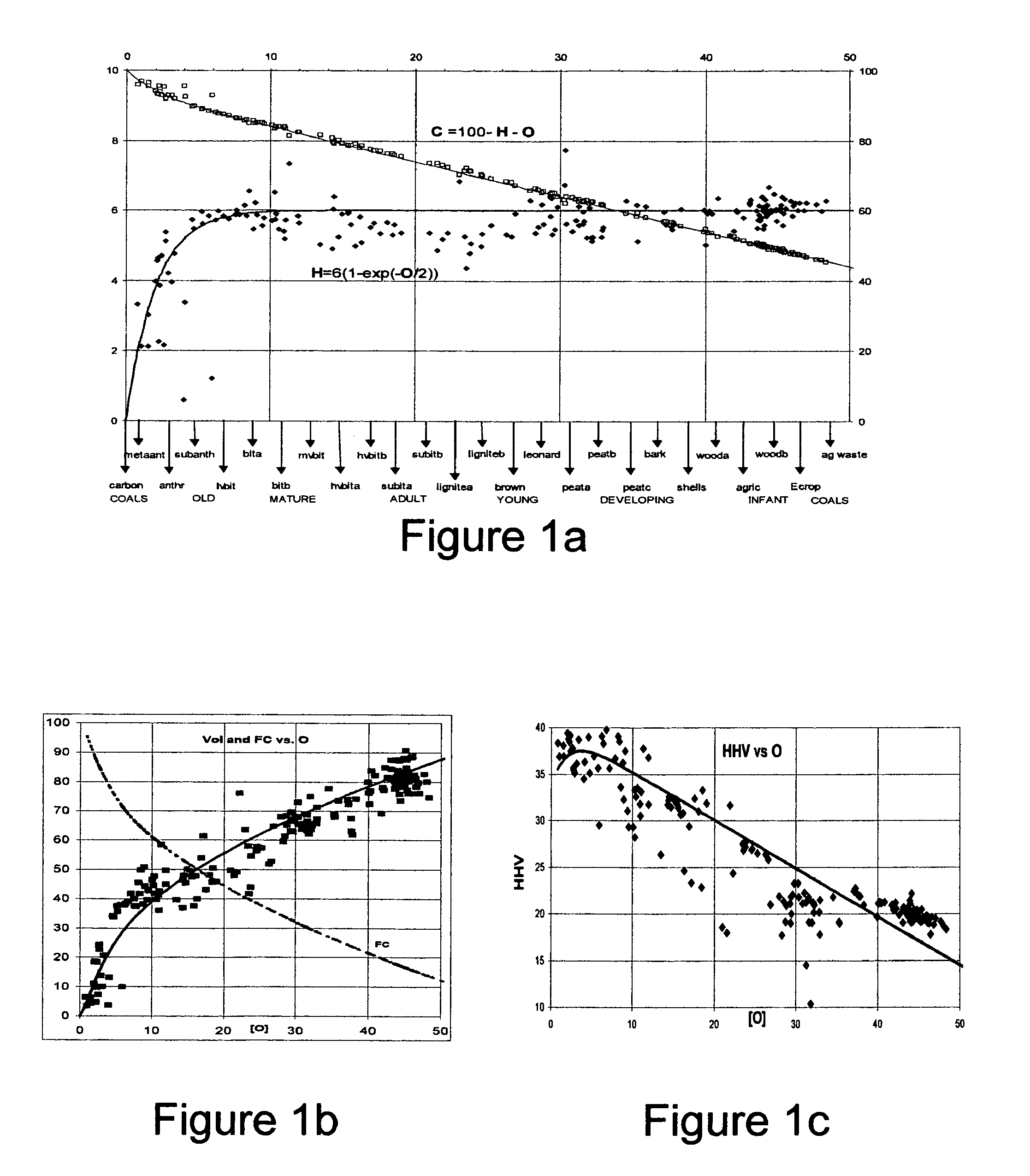
RELATED PATENTS[0001]The methods disclosed in this specification will have particular relevance to patents by the primary inventor, which include the following:[0002]Alex E. S. Green, U.S. Pat. No. 6,048,374, issued Apr. 11, 2000, “Process and device for pyrolysis of feedstock.”[0003]Alex E. S. Green, U.S. Pat. No. 6,830,597 B1, issued Dec. 14, 2004, “Process and device for pyrolysis of feedstock.”REFERENCES[0004]This invention proposes Green Pyrolyzer Gassifier (GPG) improvements to the inventions described in U.S. Pat. No. 6,048,374 (374) and U.S. Pat. No. 6,830,597 B1 (597), which are incorporated hereby by reference, for certain heat and pyro-char applications. Lists of references to external related patents are given in 597 and 374. These improvements described herein are motivated in large part by system analysis studies of the properties of various natural fuels and the nature of their pyrolysis products [references 1-20] and the relevant books and conference proceedings led ...

Claims


Application Information

Patent Timeline
Patent Type & Authority Patents(United States)
IPC IPC(8): C10B47/18C10B43/10C10B47/44C10J3/00H10N15/00
CPCC05D9/00C10B47/44C10B53/02C10G1/02C10L5/447C05F11/02Y02E50/10Y02E50/14Y02E50/30
Inventor GREEN, ALEX E. S.GREEN, BRUCE A.
Owner GREEN LIQUID & GAS TECH
Learn More