
Lignite drying water recycling and drying tail gas recycling system

A technology for drying tail gas and water, which is applied in the directions of drying solid materials, heating to dry solid materials, and drying. It can solve the problems of unavoidable volatiles such as CO, high investment, and low water recovery efficiency, so as to improve energy efficiency. Utilization efficiency and recycling level of resources, high system safety, and high recycling efficiency

Inactive Publication Date: 2014-02-12
NORTH CHINA UNIVERSITY OF SCIENCE AND TECHNOLOGY
View PDF8 Cites 23 Cited by
  • Summary
  • Abstract
  • Description
  • Claims
  • Application Information

AI Technical Summary

Problems solved by technology

Among them, the energy-saving and environment-friendly drying method and device for coal slime and lignite (publication number CN101881191A) is the prior art closest to the present invention. This method uses a heating furnace as a heat source, uses a drum dryer to dry lignite, and utilizes a heat pump unit Recovering the waste heat and moisture in the drying tail gas improves the drying efficiency of the drum dryer. However, in this patent, high-temperature flue gas is used for direct drying, which inevitably produces volatiles such as CO, and the system safety is poor. At the same time, the system uses surface Type indirect heat exchanger recovers the moisture and heat energy in the dry tail gas, the heat and mass exchange efficiency is low, the heat exchanger equipment is huge, the investment is high, and the water recovery efficiency is low

Method used


Image

  • Lignite drying water recycling and drying tail gas recycling system
  • Lignite drying water recycling and drying tail gas recycling system

Examples


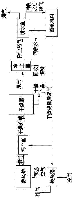
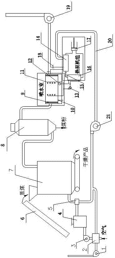
Embodiment Construction

[0025] The present invention will be further described below in conjunction with the accompanying drawings and embodiments, and the purpose is only to better understand the content of the present invention. Therefore, the examples given do not limit the protection scope of the present invention.

[0026] In this embodiment, the raw coal is dried at 100 t / h, and the total moisture content of the raw coal is dehydrated from 35% to 15% as an example for illustration. The annual average temperature of the place where the embodiment is located is 5°C.

[0027] Referring to the accompanying drawings, the air is preheated by the air preheater 2 and enters the hot blast stove 4 through the blower 3. In the hot blast stove 4, the air and coal undergo a combustion reaction to generate high-temperature hot flue gas at 900-1200°C. The dry tail gas after upgrading by the heat pump unit is fully mixed in the mixing chamber 5 into low-temperature hot flue gas at 200-350°C, and sent to the l...


PUM


Abstract

The invention relates to a lignite drying water recycling and drying tail gas recycling system which comprises a hot blast heater, a drier, a dry type deduster, a heat pump machine set, a mixing chamber and a water spraying chamber, wherein the mixing chamber is used for mixing fume of the hot blast heater and a recycled tail gas heated by the heat pump machine set into low-temperature hot fume to be used as a drying medium of the drier; the dried tail gas and the cold water sprayed out from a nozzle of the water spraying chamber are sufficiently mixed and subjected to heat-humidity exchange in the water spraying chamber; part of steam in the dried tail gas is condensed into water to be recycled; at the same time, visible heat and latent heat of vaporization are released; the cold water used in the water spraying chamber is supplied by the heat pump machine set; the water recycled in the water spraying chamber flows out through an overflowing tube and is collected. The fume discharged from the water spraying chamber is heated by an air cooling condenser of the heat pump machine set, is subsequently fed into the mixing chamber, is mixed with the fume generated from the hot blast furnace, and is subsequently used as the drying medium of the drier. The system is at a low temperature and is dry, and the oxygen content of the drying medium is low, so that volatiles in coal are prevented from being lost, and precious water resource is recycled.

Description

technical field [0001] The invention relates to lignite drying and upgrading equipment, in particular to a lignite drying water recovery and drying tail gas recycling system. Background technique [0002] Lignite has huge reserves in my country and the world. Because the water content is more than 30%, it directly participates in combustion. The evaporation process of water will take away a lot of heat energy, resulting in a large heat loss in combustion exhaust, low power generation efficiency, and a large amount of greenhouse gas emissions. Therefore, high The use of moisture lignite presents special challenges. High-moisture lignite is directly used for combustion, which not only causes unstable combustion of the boiler, but also has low efficiency. High moisture makes these coals only available locally, and it is impossible to transport them over long distances, which greatly limits the scale of coal mining. [0003] The dry upgrading of lignite rich in water is to unde...

Claims


Application Information

Patent Timeline
Patent Type & Authority Applications(China)
IPC IPC(8): F26B3/08F28C3/08B01D46/00
Inventor 钟晓晖勾昱君赵斌刘超
Owner NORTH CHINA UNIVERSITY OF SCIENCE AND TECHNOLOGY
Learn More