Interlayer dielectric film
a dielectric film and interlayer technology, applied in the direction of semiconductor/solid-state device details, manufacturing tools, transportation and packaging, etc., can solve the problems of reducing the breakdown voltage of the interlayer dielectric film disadvantageously, increasing the parasitic capacitance between adjacent interconnects, and failure of the operation of the vlsi
- Summary
- Abstract
- Description
- Claims
- Application Information
AI Technical Summary
Benefits of technology
Problems solved by technology
Method used
Image
Examples
embodiment 1
[0048]An interlayer dielectric film and a method for forming the same according to Embodiment 1 of the invention will now be described with reference to the accompanying drawings.
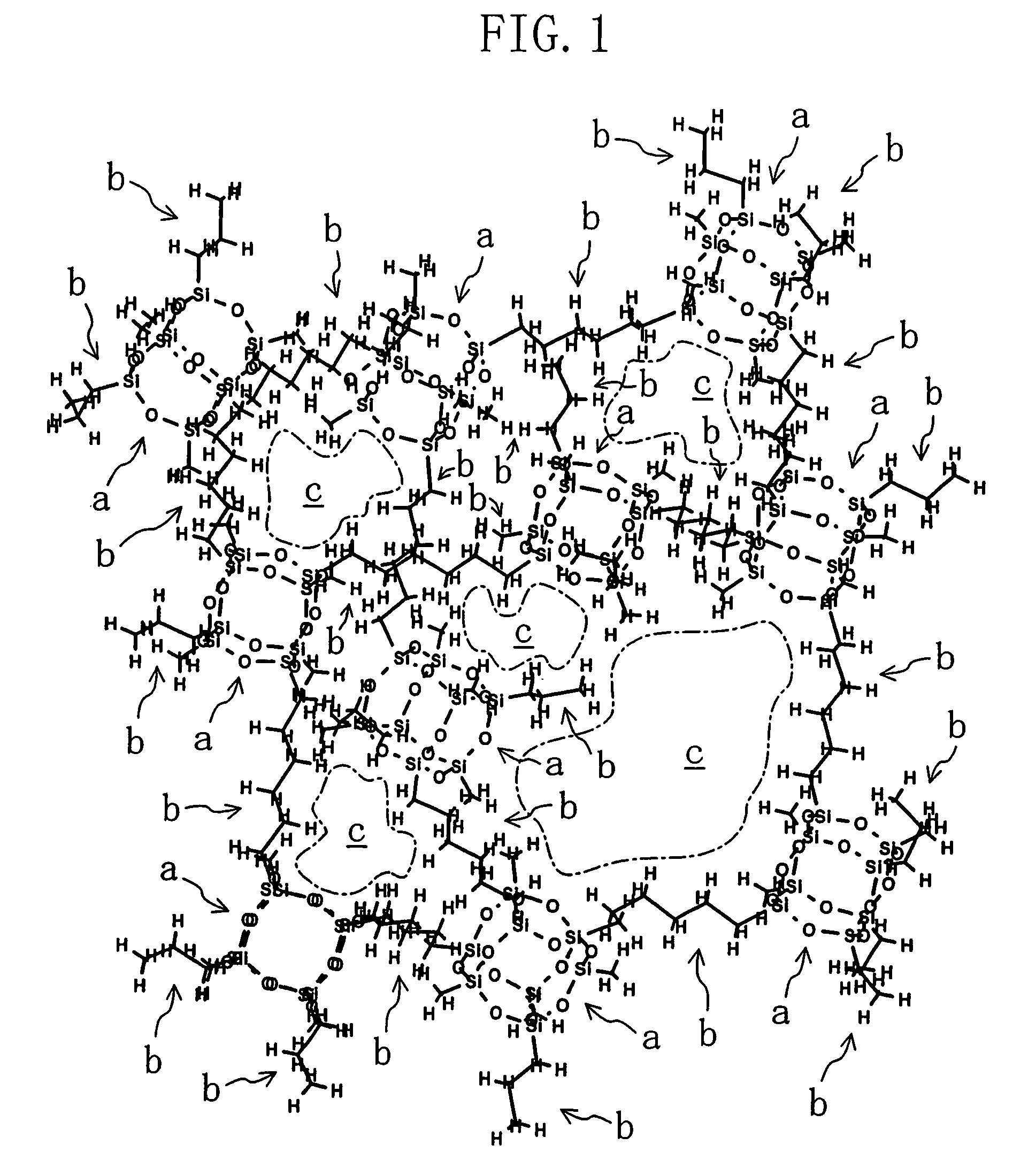
[0049]FIG. 1 shows the molecular structure of an organic / inorganic hybrid film corresponding to the interlayer dielectric film of Embodiment 1. In FIG. 1, a indicates a first site composed of siloxane, b indicates a second site composed of an organic molecule and c indicates a free volume.
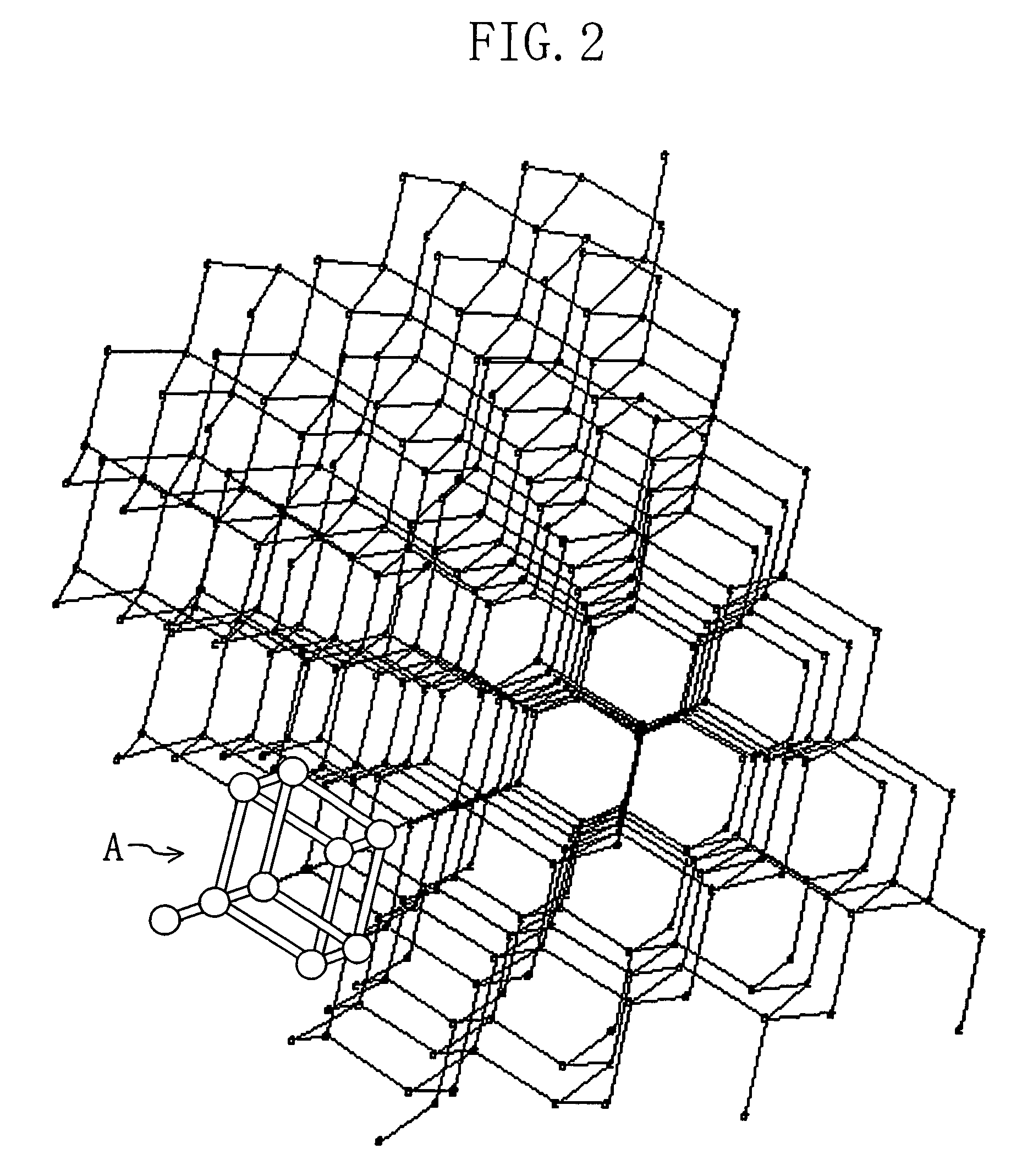
[0050]FIG. 2 is a conceptual diagram for showing the molecular structure of the organic / inorganic hybrid film corresponding to the interlayer dielectric film of Embodiment 1.
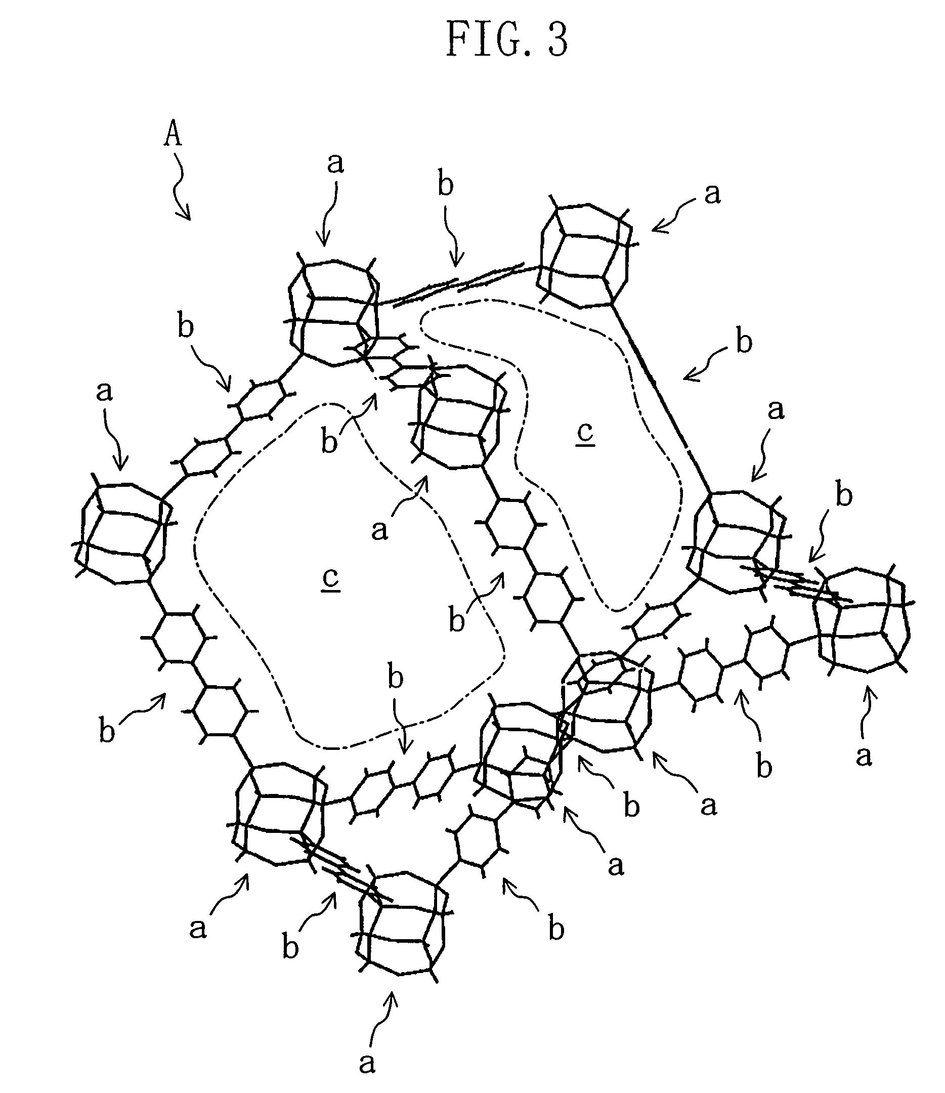
[0051]FIG. 3 roughly shows the molecular structure of a region A of FIG. 2, wherein a indicates the first site composed of siloxane, b indicates the second site composed of the organic molecule and c indicates the free volume.
[0052]FIG. 4 schematically shows the molecular structure of the region A of FIG. 2.
[0053]FIG. 5 three-dimensionally shows a bond...
embodiment 2
[0075]An interlayer dielectric film and a method for forming the same according to Embodiment 2 of the invention will now be described with reference to the accompanying drawing.
[0076]The interlayer dielectric film of Embodiment 2 includes a plurality of first sites a each composed of siloxane and a plurality of second sites b each composed of an organic molecule. The plural second sites b together form an organic polymer film, in which the plural first sites a and a plurality of holes c are dispersed. In this case, the first site a composed of siloxane may be or may not be bonded to the second site b composed of the organic molecule.
[0077]FIG. 12 shows the cross-sectional structure of the interlayer dielectric film of Embodiment 2. As shown in FIG. 12, in the interlayer dielectric film formed on a semiconductor substrate 10, a plurality of silica fine particles 12 each corresponding to the first site a and a plurality of holes 13 are dispersed in an organic polymer film 11 formed f...
embodiment 3
[0084]An interlayer dielectric film according to Embodiment 3 of the invention will now be described with reference to the accompanying drawing.
[0085]FIG. 13 shows the cross-sectional structure of the interlayer dielectric film of Embodiment 3. As shown in FIG. 13, a lower interlayer dielectric film 21 and an upper interlayer dielectric film 22 are successively formed on a semiconductor substrate 20. A lower copper interconnect 23 is buried in the lower interlayer dielectric film 21, and an upper copper interconnect 24 is buried in the upper interlayer dielectric film 22.
[0086]As shown in FIG. 13, each of the lower and upper interlayer dielectric films 21 and 22 is made from a multi-layer film composed of a first layer d of siloxane and a second layer e of an organic molecule alternately stacked.
[0087]Since the first layer d of siloxane and the second layer e of the organic molecule are alternately stacked in the interlayer dielectric film of Embodiment 3, the lower copper interconn...
PUM
| Property | Measurement | Unit |
|---|---|---|
| particle size | aaaaa | aaaaa |
| distance | aaaaa | aaaaa |
| dielectric | aaaaa | aaaaa |
Abstract
Description
Claims
Application Information
 - R&D
- Intellectual Property
- Life Sciences
- Materials
- Tech Scout
- Unparalleled Data Quality
- Higher Quality Content
- 60% Fewer Hallucinations
Browse by: Latest US Patents, China's latest patents, Technical Efficacy Thesaurus, Application Domain, Technology Topic, Popular Technical Reports.
© 2025 PatSnap. All rights reserved.Legal|Privacy policy|Modern Slavery Act Transparency Statement|Sitemap|About US| Contact US: help@patsnap.com


