Image pickup lens, image pickup device, and mobile terminal device

a pickup lens and image technology, applied in the field of small thin image pickup lenses, can solve the problems of insufficient correction of chromatic aberration of magnification, large image field curvature, and inability of image pickup lenses to respond to high pixel density, etc., to achieve high density pixels, small size, and high performance

Active Publication Date: 2011-05-24
KONICA MINOLTA OPTO
View PDF11 Cites 6 Cited by
  • Summary
  • Abstract
  • Description
  • Claims
  • Application Information

AI Technical Summary

Benefits of technology

[0028]Furthermore, when the core thickness of the second lens is set so as to exceed the lower limit of the conditional formula (2), a light flux which has diverged on the object side surface of the second lens can converge effectively on the image side surface, whereby the telecentric property can be improved. In addition, a light flux having entered the second lens diverges on the object side concave surface of the second lens, and then light rays of the light flux are separated for each image height and emitted from the image side surface of the second lens. Further, when the core thickness of the second lens is set so as to exceed the lower limit of the conditional formula (2), the light rays of the light flux can be separated sufficiently for each image height, whereby it becomes easy to correct aberration for each image height by the aspheric surface of the image side surface of the second lens. On the other hand, when the core thickness of the second lens is set to be less than the upper limit of the conditional formula (2), it becomes possible to obtain an image pickup lens whose overall length does not become large excessively. At this time, since the peripheral region of the second lens has a positive power for off-axis light rays, a magnification chromatic aberration becomes large. However, when an Abbe's number is made large as specified in the conditional formula (3), the occurrence of the magnification chromatic aberration can be suppressed, whereby the chromatic aberration can be corrected up to a peripheral region of an image plane with a small number of lenses and it becomes possible to attain an optical system corresponding to high density pixels with a high performance and small size.
[0110]According to the present invention, it is possible to provide an image pickup lens which corrects chromatic aberration up to a peripheral region of an image taking plane with a small number of lenses and corresponds to image pickup elements which has a high performance with a small size and comprises high density pixels, and an image pickup device and a mobile terminal device which employs the image pickup lens.

Problems solved by technology

However, in the image pickup lenses disclosed by the Patent Documents 1 and 2, all lenses are constituted with positive lenses, and astigmatic is not corrected sufficiently so that the image pickup lenses cannot respond sufficiently to the high pixel density.
However, there is a problem that curvature of image field is large or chromatic aberration of magnification is not corrected sufficiently.

Method used


Image

  • Image pickup lens, image pickup device, and mobile terminal device
  • Image pickup lens, image pickup device, and mobile terminal device
  • Image pickup lens, image pickup device, and mobile terminal device

Examples


example 1

[0186]The lens data of Example 1 are shown in Table 1. FIG. 8 is a cross sectional view of the image pickup lens of Example 1. FIG. 9 shows aberration diagrams (spherical aberration (FIG. 9a), astigmatism (FIG. 9b), distortion aberration (FIG. 9c)) of Example 1. FIG. 10 is a magnification chromatic aberration diagram of Example 1. Here, in the spherical aberration diagram, a solid line indicates a spherical aberration amount ford spectral line, a broken line indicates a spherical aberration amount for g spectral line, and a dotted line indicates a spherical aberration amount for c spectral line, respectively. Further, in the astigmatism aberration diagram, a solid line indicates a sagittal surface and a dotted line indicates a meridional surface, and in the magnification chromatic aberration diagram, a solid line indicates the difference between g spectral line and C spectral line, and a dotted line indicates the difference of g spectral line and d spectral line, respectively (herea...

example 2

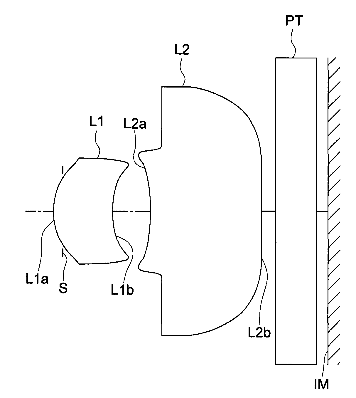
[0188]The lens data of Example 2 are shown in Table 2. FIG. 11 is a cross sectional view of the image pickup lens of Example 1. FIG. 12 shows aberration diagrams (spherical aberration (FIG. 12a), astigmatism (FIG. 12b), distortion aberration (FIG. 12c)) of Example 2. FIG. 13 is a magnification chromatic aberration diagram of Example 2. The image pickup lens of Example 2 comprises, in the order from the object side, an aperture stop S, a positive meniscus lens L1 having a convex optical surface L1a at the object side and a concave optical surface L1b at the image side, a negative meniscus lens L2 having a concave optical surface L2a at the object side and a convex optical surface L2b at the image side, an optical low pass filter, an infrared cut off filter, and a parallel plate PT supposing as a seal glass of a solid state image pickup element IM is an image pickup plane of the image pickup element. All surfaces of a lens section coming in contact with air are made in an aspheric con...

example 3

[0190]The lens data of Example 3 are shown in Table 3. FIG. 14 is a cross sectional view of the image pickup lens of Example 3. FIG. 15 shows aberration diagrams (spherical aberration (FIG. 15a), astigmatism (FIG. 15b), distortion aberration (FIG. 15c)) of Example 3. FIG. 16 is a magnification chromatic aberration diagram of Example 3. The image pickup lens of Example 3 comprises, in the order from the object side, an aperture stop S, a positive meniscus lens L1 having a convex optical surface L1a at the object side and a concave optical surface L1b at the image side, a negative meniscus lens L2 having a concave optical surface L2a at the object side and a convex optical surface L2b at the image side, an optical low pass filter, an infrared cut off filter, and a parallel plate PT supposing as a seal glass of a solid state image pickup element IM is an image pickup plane of the image pickup element. All surfaces of a lens section coming in contact with air are made in an aspheric con...


PUM


Abstract

An image pickup lens, comprises sequentially from an object side: an aperture stop, a first lens being a positive meniscus lens which has a convex surface at the object side and a concave surface at an image side opposite to the object side, and a second lens having a concave surface at the object side and an image side surface whose radius of curvature on an paraxial region is infinite or a negative value, wherein the first lens is the second lens and the image side surface of the second lens includes an aspheric surface to make a positive power strong toward a lens peripheral region, and wherein the image pickup lens is made to satisfy the following conditional formulas:1.55<n1<1.80  (1)0.4<D3 / f<0.6  (2)40.0<ν2<90.0  (3).

Description

[0001]This application is based on Japanese Patent Application No. 2009-152054 filed on Jun. 26, 2009, and Japanese Patent Application No. 2010-035062 filed on Feb. 19, 2010, in Japanese Patent Office, the entire content of which is hereby incorporated by reference.TECHNICAL FIELD[0002]The present invention relates to an image pickup lens, and in particular, relates to a small thin image pickup lens suitable for being incorporated into a notebook PC and a mobile terminal device and to an image pickup device and a mobile terminal device employing it.BACKGROUND ART[0003]In recent years, small thin image pickup devices have been incorporated in a mobile terminal device which is a small thin electronic device such as a mobile telephone, a PDA (Personal Digital Assistant) and the like, whereby it becomes possible to transmit not only voice information but image information to a remote place mutually among the mobile terminal devices.[0004]As an image pickup element used for these image p...

Claims


Application Information

Patent Timeline
Patent Type & Authority Patents(United States)
IPC IPC(8): G02B13/18G02B9/04
CPCG02B7/022G02B13/003H04N5/2251H04N5/2257G02B27/0025Y10T156/1052G02B13/0015H04N23/57
Inventor FUKUTA, YASUNARISATO, MASAEKAWASAKIMATSUI, KAZUKI
Owner KONICA MINOLTA OPTO
Why Eureka
Try Eureka