Laser optics integrated control system and method of operation

a technology of integrated control system and laser transmitter, which is applied in the field of laser transmitter feedback control system, can solve the problems of limited scope of disclosure, levinson does not appear to disclose an integrated circuit solution, and limit the teaching of levinson, so as to facilitate interconnection and compatibility, increase reliability, and reduce the cost of laser transmitter

Inactive Publication Date: 2011-05-24
OL SECURITY LIABILITY CO +1
View PDF22 Cites 45 Cited by
  • Summary
  • Abstract
  • Description
  • Claims
  • Application Information

AI Technical Summary

Benefits of technology

[0014]In reference to FIG. 3, the control system (200) consists of an apparatus containing a digital controller IC (320), a driver (301), a set of sensors (306,307,309,319) and digital control methods embedded in controller IC (320). The control system contains the necessary features to control the various operational parameters of the Laser Module (303).The control first starts with a modulation drive signal (300); the drive signal causes the circuits in the driver (301) to send an appropriate signal to the output (302) so that the laser can send an optical power output (304) proportional to the input signal (300). The Laser Module (303) may contain a semiconductor laser or a VCSEL laser array and also may contain the necessary features to tune the laser wavelength. The control methods embedded in Laser Controller IC (320) consist of control algorithms embedded in firmware. The Laser Controller IC (320) includes the necessary support circuits for control of a laser. The circuits in the controller may include among other circuits digital functions such as a processor, ROM, RAM non volatile RAM, clock, reset, I / O. Mixed analog and digital features include one or more digital to analog converters, potentiometer, sample and hold amplifiers, analog multiplexer, programmable gain amplifier analog multiplexer, programmable gain amplifier, analog to digital converter, operational amplifiers. Power control circuits include a laser power control latch, a laser power switch and a laser overvoltage and transient control protection circuit. Other possible circuits may include optical link characterization support circuits such as a precision voltage reference and a reference drive switch for analog signal support and a set of Optical Link Characterization circuits, which provide support for such as bit error rate determination.The control system architecture can control one or more lasers or a VCSEL array by a change in the type of driver. Some of the distinguishing features of the control system in the present invention from the prior art are:Feedback information from the sensors is obtained in a synchronous manner as a “snapshot” of the laser performance utilizing either Sample / Hold devices or by very rapid sampling of the feedback information.Algorithms handle the entire set of controls in firmware and do not rely on analog closed loop controls. This feature allows for advanced controls, which precisely stabilize the laser, can accommodate adaptive controls and can be leveraged from one laser transmitter design to another.
[0016]Another novel feature of the present invention is that the control processes implemented in the algorithms define the “plant characterization”. This information fully characterizes the laser and sensors. Preferably, the characterization is carried out only during product development rather than during production test. The characterization allows for a precise real-time control of the laser.
[0019]Yet another unique feature of the present invention is that a complete set of specialized features needed for laser feedback control systems are incorporated into one integrated circuit, which substantially increases reliability and reduces cost of the laser transmitter.
[0020]Finally, other novel features of this invention are in the Methods of Operation. These methods include a real time operating system for a laser transceiver. The operating system allows for a structured approach that offers significant leveraging of the firmware resources by the different programs that are embedded in the controller. In addition, the operating system facilitates interconnection and compatibility of firmware programs written by different programmers in a standardized manner, which promotes leveraging of programs from one product generation to another and also allows programs from various vendors to connect to each other in an orderly fashion.

Problems solved by technology

Although a programmed microcontroller is disclosed, a limitation to Levinson is the teaching is to only “ .
. . preventing light from the laser diode's from accidentally damaging user's eyes.” Levinson does not appear to disclose an integrated circuit solution.
. . “During operation, an embedded microcontroller together with analog to digital converters, digital to analog converters and other associated circuitry, dynamically control the operational parameters (e.g. modulation and bias current) based on the current operating conditions (temperature, power supply).” A limitation of King, et al is the limited scope of the disclosure.
Because of that reason this implementation reduces the possibilities for modifications and the possibilities for leveraging from one product generation to another.
The analog circuits utilize complex analog topologies, which are difficult to leverage, support and calibrate.
The analog parts also require a significant effort in maintaining component quality in production.
Other deficiencies of analog control systems are in the way the control algorithms are implemented.
Prior solutions do not effectively leverage solutions from one product to another because they are based on fixed hardwired design implementations of a control system.
This situation causes a larger set of packages to be utilized increasing costs and decreasing reliability.
Another issue of the known prior art methods is that complex issues need to be decided very early in the projects.

Method used


Image

  • Laser optics integrated control system and method of operation
  • Laser optics integrated control system and method of operation
  • Laser optics integrated control system and method of operation

Examples


Embodiment Construction

Apparatus

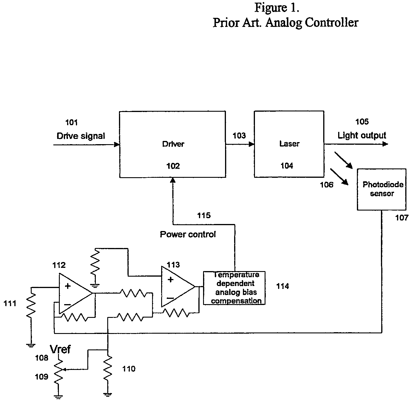
[0026]FIG. 1 illustrates a typical analog control system from prior art. This control system utilizes analog controllers. Adjustment of laser power with changes in temperature is done by a temperature sensitive device, which adds compensation current to the laser drive. This approach is made with fixed controls that need to be hardwired for each application. Because of that reason this implementation reduces the possibilities for modifications and the possibilities for leveraging from one product generation to another.

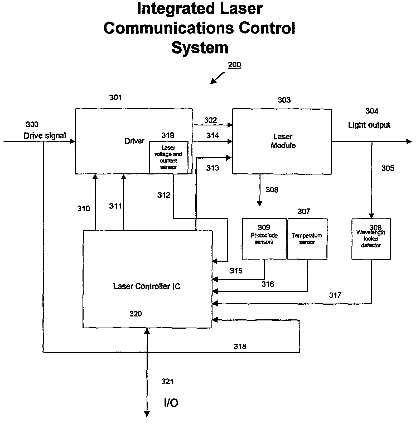
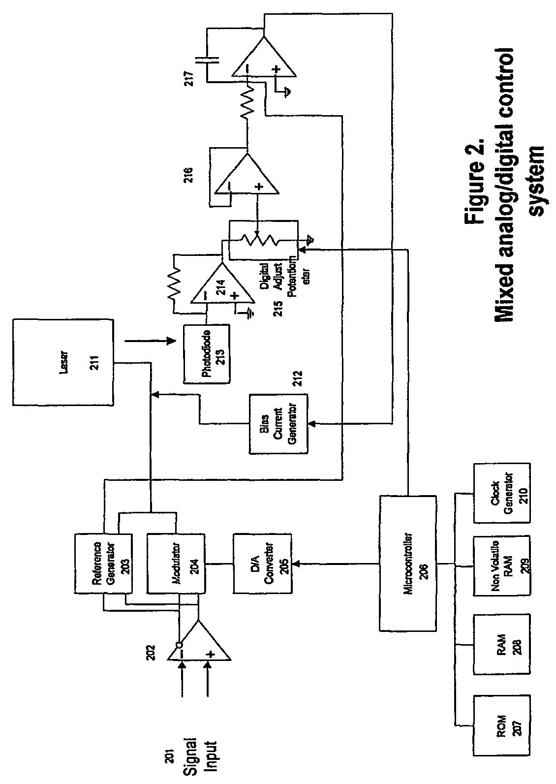
[0027]FIG. 2 illustrates a mixed analog / digital control system from prior art. This system is an example of a more elaborate control system. The system accommodates an initial characterization of the laser at all temperatures. In this control system, a photodiode-monitoring laser output power is used as feedback. It is significant that in FIG. 2, the control loop is still an analog control loop. The difference between the loop in FIG. 2 and a digital control l...


PUM


Abstract

A controller (320) for controlling various operational parameters of the Laser Module (303). The modulation drive signal (300) causes the circuits in the driver (301) to send a signal to the output (302) so that the laser can send an optical power output (304) proportional to the drive signal (300). The control methods in Laser Controller IC (320) consist of control algorithms embedded in firmware. The Laser Controller IC (320) includes support circuits for control of a laser. Some of the distinguishing features in the present invention are 1) feedback information from the sensors is obtained in a synchronous manner as a snapshot of the laser performance, and 2) algorithms handle the entire set of controls in firmware. The algorithm feature allows for advanced servo controls, which precisely stabilize the laser, can accommodate adaptive controls, and can be leveraged from one laser transmitter design to another.

Description

CROSS REFERENCES TO RELATED APPLICATIONS[0001]This application is a U.S. national stage entry under 35 U.S.C. § 371of PCT / US2002 / 040940, filed Dec. 21, 2002, which in turn claims priority to provisional application Ser. No. 60 / 344,177, filed Dec. 27, 2001, entitled “Integrated Communications Controller and Method of Operation.”BACKGROUND[0002]The invention relates to a Laser Feedback Control System. The control system utilizes algorithms of modern digital controls and utilizes a laser controller Integrated Circuit. Use of edge emitter lasers for high performance long haul and metropolitan networks will continue in high performance applications including wavelength division multiplexing. VCSEL arrays have been used increasingly in fiber optics telecommunication due to their low cost. Widespread use will place increasing demands on performance of all elements of the electrical to optical interface. Increasing speed of computers will place increased demands on the performance of transm...

Claims


Application Information

Patent Timeline
Patent Type & Authority Patents(United States)
IPC IPC(8): H01S3/00H01S5/06H01S5/068H04B10/12H04B10/155
CPCH01S5/068H04B10/572H04B10/504H04B10/564H01S5/0612H01S5/06804H01S5/0683H01S5/423H01S5/0687
Inventor OLEA, JORGE SANCHEZ
Owner OL SECURITY LIABILITY CO
Why Eureka
Try Eureka