FPGA-based network device testing equipment for high load testing

a network device and testing equipment technology, applied in the field of network device testing equipment, can solve the problems of large time-consuming, large circuit size of the procedure to compare the transmitted packet with the received packet, and high workload of the test, and achieve high media speed and high load

Inactive Publication Date: 2011-05-31
NAT INST OF ADVANCED IND SCI & TECH +2
View PDF11 Cites 116 Cited by
  • Summary
  • Abstract
  • Description
  • Claims
  • Application Information

AI Technical Summary

Benefits of technology

[0010]The present invention makes it easy to exert a high load in a test using a small packet, thereby making it possible to perform tests at a sufficiently high media speed (speed of the physical layer of 1 Gpbs or 10 Gpbs, for example).
[0011]This invention makes it possible to measure the performance of the network device at present in an ultimate condition applicable also to the Ethernet exceeding 10 Gpbs. Furthermore, since the present invention makes it possible to induce a DoS attack, it can inspect whether or not a device under measurement has a fragile nature in this aspect.
[0014]In view of the above, the network device testing equipment according to the present invention has a configuration which comprises a transmitter, a receiver, a transmission channel connecting the transmitter, a device to be inspected and the receiver, means for setting inspection packets and a parameter on the transmitter, means for comparing data from the transmitter and receiver, means for calculating inspection table, means for collecting inspection tables and means for calculating and outputting inspection results. A series of packets are produced directly from an FPGA in the transmitter connected to a PHY chip of a network. This configuration provides high-speed characteristics and controllability of a packet configuration and inter-packet gap. When a device to be tested can receive a plurality of inputs, a test under a modified timing between the plural inputs can also be performed.
[0015]In the present invention, the transmitter includes a plurality of field programmable gate arrays connected to the physical layer chip to switch the arrays or a partially rewritable field programmable gate array to switch a circuit for packet sent, thereby enabling various kinds of tests, even if more complicated, to be performed.
[0017]Also in the present invention, the transmitter comprises means for randomizing frame data, means for calculating hash values of the transmitted data and means for comparing the frequencies on the transmitting and receiving sides every one packet to confirm the presence and absence of the arrival of the packets. In the case of the packets to be filtered, only confirmation of not receiving the filtered packets will be required. This is easy to perform.

Problems solved by technology

Such restrictions cause problems in high load tests using a small packet.
However, the following problems are imposed.(P1) The required memory size for recording the packets becomes huge.(P2) A separate communication channel having the same bandwidth as the Ethernet path to be examined is required for transferring the transmitted packet data to the examination section of the receiver.(P3) The procedure to compare the transmitted packets with the received packets requires a large scale of circuits and is time-consuming.
Though there is a performance measuring apparatus using ASICs (Application Specific Integrated Circuits) for a network device, since specifically designed chips are required, the performance measuring apparatus is inclined to be very expensive in spite of low degree of freedom of the test items.

Method used


Image

  • FPGA-based network device testing equipment for high load testing
  • FPGA-based network device testing equipment for high load testing
  • FPGA-based network device testing equipment for high load testing

Examples


example 1

[0045]In the following description, test equipment having the following function is intended.[0046]1) Measurement of Throughput and Average Packet Length:

[0047]A function to deal with any packet from a packet of 64 bites to a jumbo packet and to measure the average packet length is mounted. In any packet size, it is possible to measure the throughput up to the theoretical maximum value.[0048]2) Inspection of Frame-Transmitting and Frame-Receiving Sequences:

[0049]A function to inspect any frame sequence including an Inter Frame Gap (IFG) and a preamble is mounted. It is possible to accurately grasp the behavior of a network device at the time of error occurrence.[0050]3) Verification of URL Filtering Function:

[0051]A function to verify the behavior of a URL filter used to restrict accessing to malicious homepages is mounted. It is possible to inspect high-speed filtering function at low realization cost using a hash table. It is also possible to measure the throughput while inspectin...

example 2

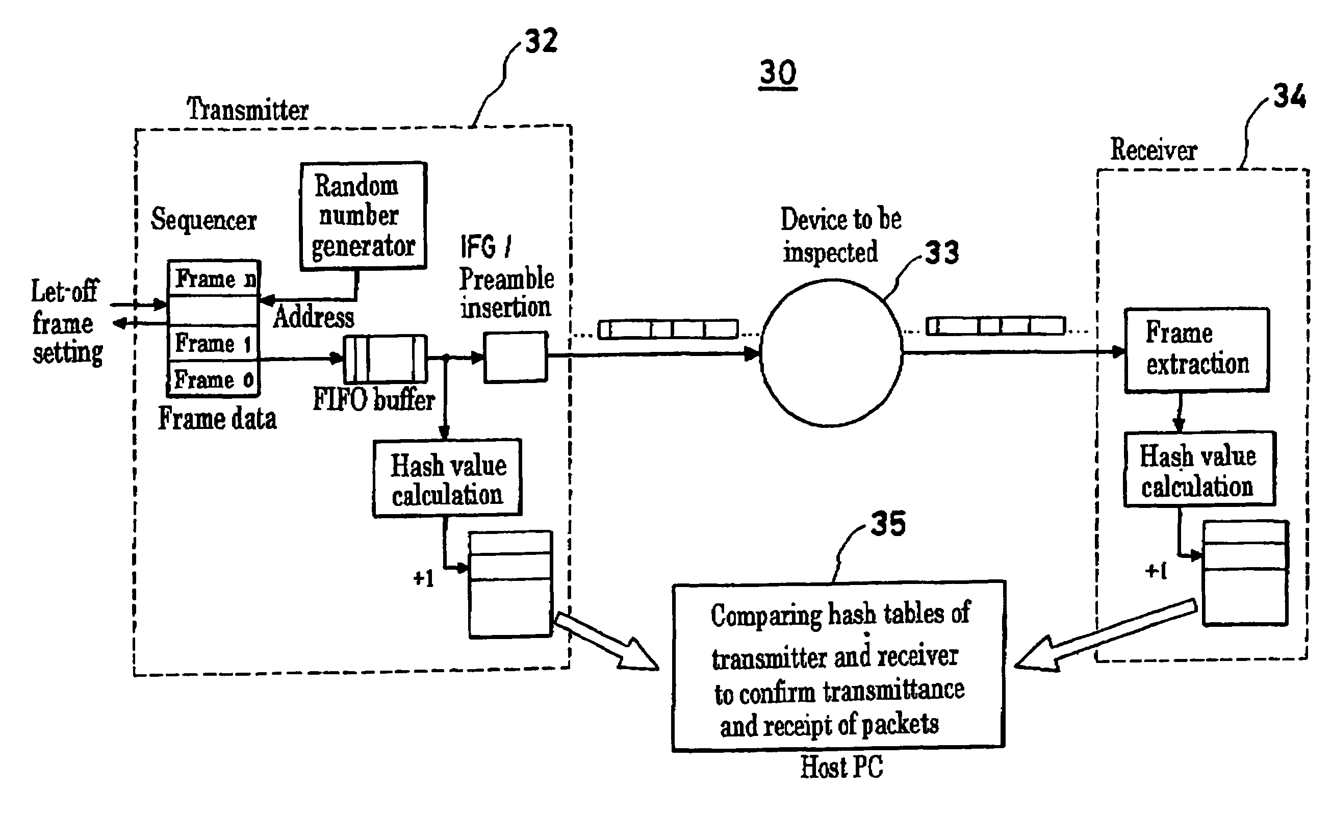
[0062]A device for inspecting frame transmitting and receiving sequences will next be described FIG. 6 shows a schematic diagram of a device for producing and recording frame transmitting and receiving sequences that include frame data, an inter-frame gap and a preamble. In this device, since it is possible to analyze a frame sequence having the length of an inter-frame gap and the length of a preamble recorded therein, it is possible to inspect the behavior of a network device that receives data suffered from errors in the network. By analyzing the interval between the frames sent by the network device, it is also possible to investigate the cause of a decreased throughput. A host PC configures a frame to be transmitted and its sequence in a transmitter, obtains the sequences to sort the received frames from a receiver, analyzes data and provides an output.

[0063]A block diagram of the transmitter 62 of the device shown in FIG. 6 is shown in FIG. 7 and a block diagram of the receive...

example 3

[0065]Next, a device for measuring a throughput and an average packet length will be described. FIG. 9 is a block diagram showing a transmitter of the device for measuring a throughput and an average packet length according to the present invention. FIG. 10 is a block diagram showing a receiver thereof.

[0066]The transmitter of FIG. 9 sets parameters on a packet sent from a host PC 95 to a frame generator 91, and the frame generator 91 continuously generates the packets after a sequence is designated using a PHY chip 96.

[0067]The receiver of FIG. 10 allows the data received from the PHY chip 96 to pass through a frame detector 101 formed in an FPGA or ASIC, the byte count of a frame received is recorded on a byte counter 102, packets are discriminated at a packet detector 103 and the discriminated packets are recorded using a packet counter 105. This measurement is made per unit time in accordance with a trigger signal from a timer 106, and a sequencer 107 outputs throughput data and...


PUM


Abstract

Network device testing equipment capable of testing network devices using small size packets and for a transferring ability and a filtering ability at a media speed is described. A configuration is adopted in which a Field Programmable Gate Array (FPGA) included in a transmitter or receiver on one or both of transmitting and receiving sides is connected directly to a physical layer chip of a network and computers on both the transmitting and receiving sides are connected thereto. Each of the FPGAs of the transmitter and receiver has a circuit which has an integrated function of transmitting a packet pattern generation function and a packet-receiving function, thereby enabling a test and an inspection in real time. When inspecting the filtering function, a hash table storing therein a hash value and a list of occurrence frequencies for hash values is utilized. In order to avoid the hash values of different packets from having a same value, the hash function is configured so as to avoid that the same hash value is given to different packets or, when packet values have a common hash value, the packet is re-shaped into a packet having a different hash value.

Description

BACKGROUND OF THE INVENTION[0001]1. Field of the Invention[0002]The present invention relates to network device testing equipment for testing network devices used in a network and related fields including Ethernet communications and Internet.[0003]2. Description of the Prior Art[0004]To filter out computer viruses or unwanted URLs (Uniform Resource Locators) in the network, it is necessary to confirm both the filtering function and the filtering performance that discriminates packets to be blocked and packets not to be blocked. In particular, the behavior of the network device is important when having received a DoS attack (Denial of Service Attack) that is known for modifying the function return address to invade by perpetually sending small-sized packets until the packet buffer overflows.[0005]Personal computers are often used in equipment for testing network devices taking advantage of its versatility and the communication function installed in it. The equipment suffers restricti...

Claims


Application Information

Patent Timeline
Patent Type & Authority Patents(United States)
IPC IPC(8): H04L12/26G01R31/08G06F11/00G06F7/04H04L29/08H04L69/40G06F13/00
CPCH04L43/50H04L12/2697
Inventor TODA, KENJIKATASHITA, TOSHIHIROSAKAMAKI, KAZUMIINUI, TAKESHINAGOYA, MITSUGUTERASHIMA, YASUNORI
Owner NAT INST OF ADVANCED IND SCI & TECH
Why Eureka
Try Eureka