Wood fired boiler

a biomass fueled stove and boiler technology, which is applied in the direction of domestic stoves or ranges, combustion types, furnaces, etc., can solve the problems of many existing wood fueled stoves and boilers that are relatively inefficient, and achieve the effects of facilitating cold starts, reducing back draft, and facilitating carbon removal

Active Publication Date: 2011-06-07
CENTRAL BOILER
View PDF7 Cites 1 Cited by
  • Summary
  • Abstract
  • Description
  • Claims
  • Application Information

AI Technical Summary

Benefits of technology

[0017]It is further object of the invention to provide a boiler or stove including one or more alternative fuel fired burners to facilitate the reduction of hydrocarbon emissions and / or cold startups and / or adjust operation to fuel costs and availability.
[0018]It is further object of the invention to provide a boiler or stove including baffles and air control assemblies to restrict back drafts.
[0024]The fire tubes preferably project at an acute angle in the range of 45 to 80 degrees versus conventional fire tubes that typically lay horizontal and / or may wind in a horizontal serpentine path. The angular displacement of the present fire / exhaust tubes facilitates carbon removal from the tubes. That is, gravity directs ash and carbon falling from the tubes back into the secondary burn / ash chamber where the carbonized ash and solids from the primary burn chamber are continually subjected to secondary combustion.
[0025]A tertiary burner can be fitted to the primary burn chamber to facilitate cold starts and / or provide for boiler operation with a secondary fuel (e.g. gas—natural or propane, oil or other petrochemical fuels). A second gas fired burner and pressurized combustion air supply can also be provided at the secondary burn / ash chamber. The tertiary gas fired burner(s) sustains combustion of the exhaust gases during startup and low temperature stove conditions.

Problems solved by technology

Many existing wood fueled stoves and boilers are relatively inefficient and exhaust smoke and flue gases that contain high concentrations of hydrocarbons that are hazardous to the environment.

Method used


Image

  • Wood fired boiler
  • Wood fired boiler
  • Wood fired boiler

Examples


Embodiment Construction

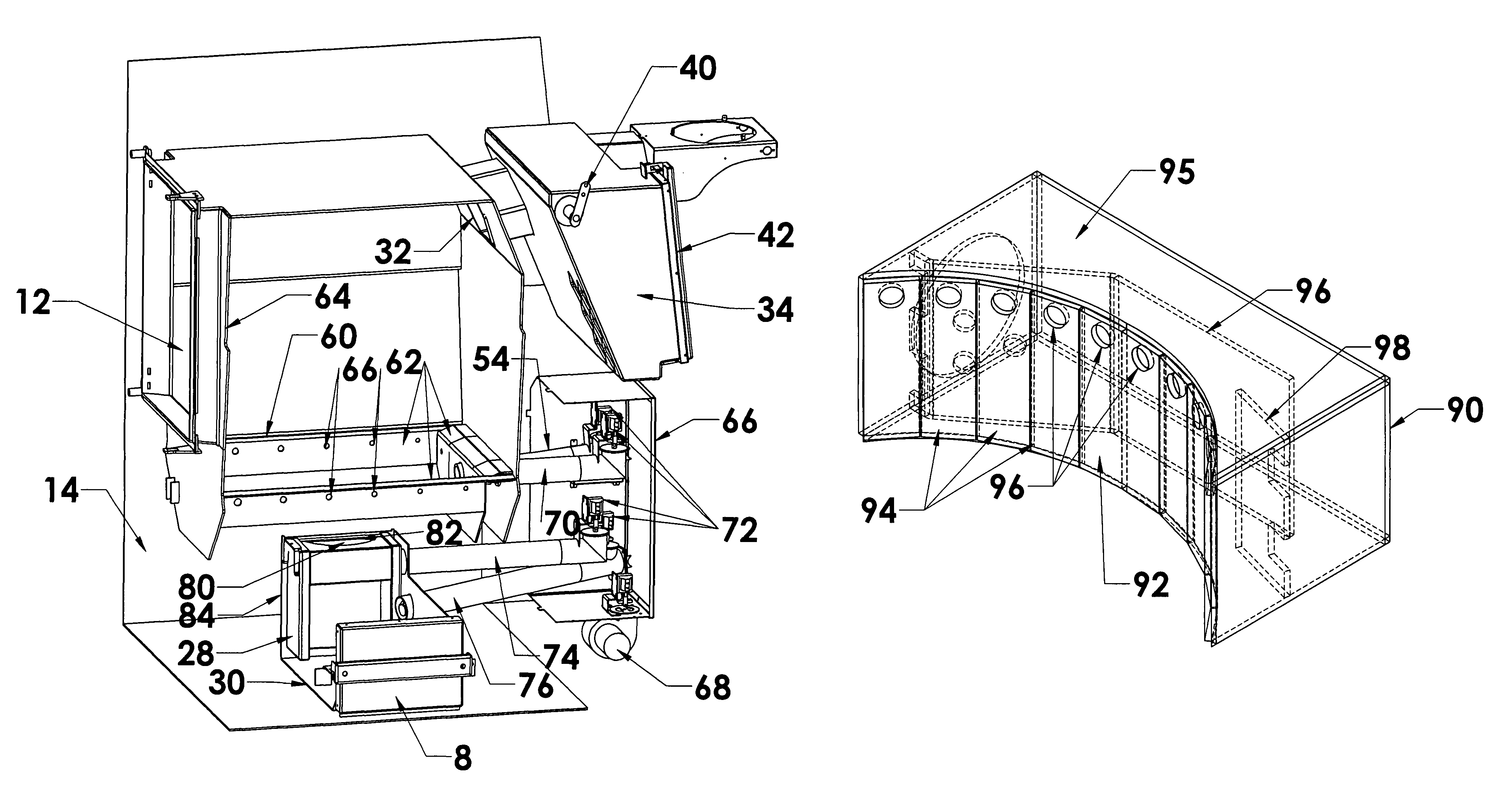
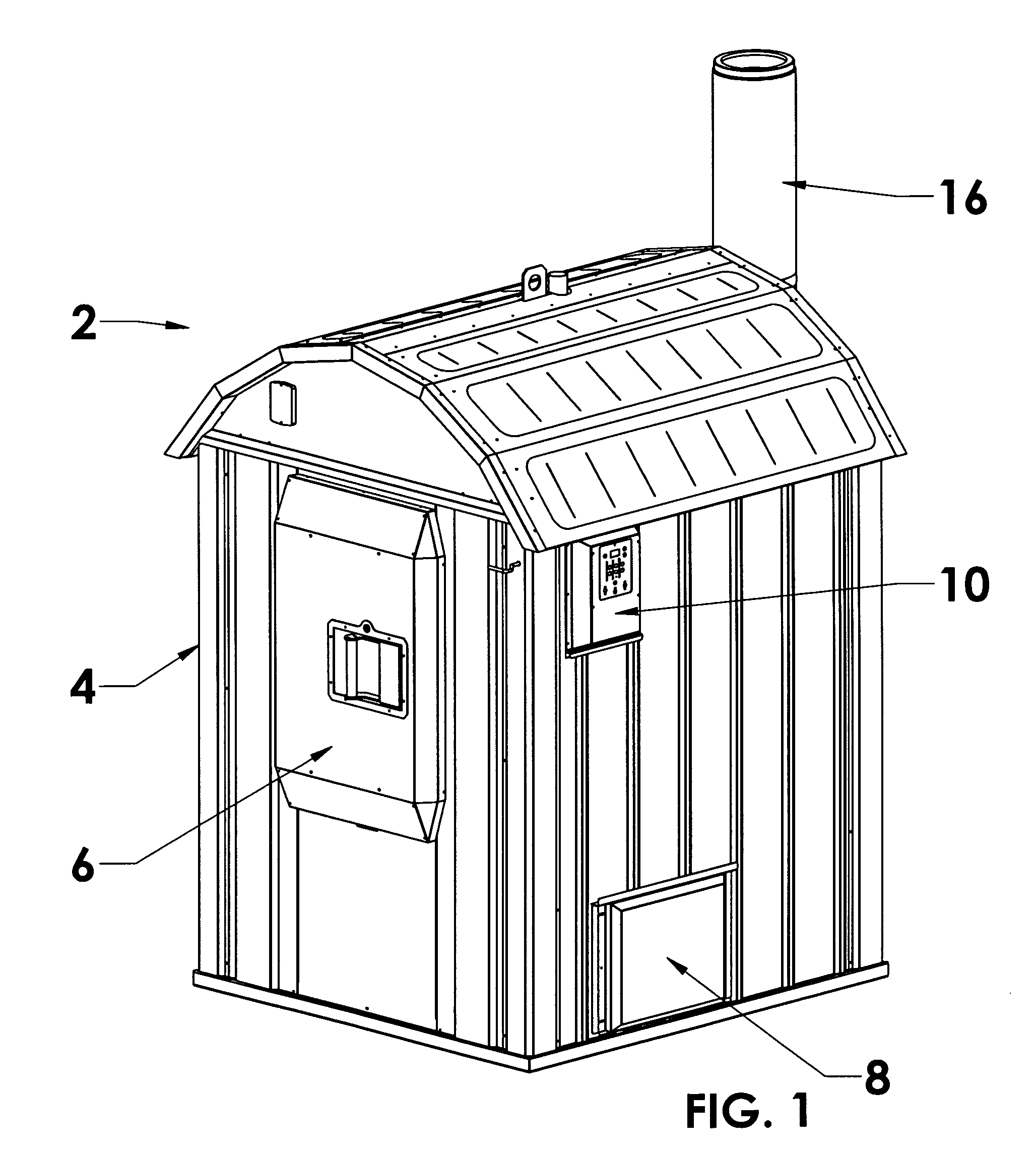
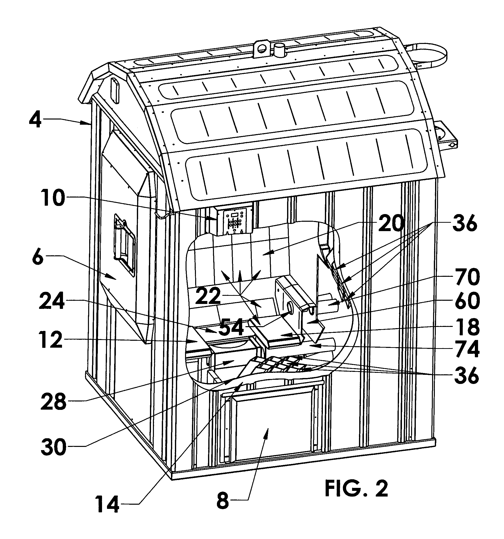
[0050]Referring to FIGS. 1 through 5, several views are shown to the general external and internal construction of the biomass fueled stove and boiler assembly 2 of the invention. The boiler 2 is compatible with wood, coal, manufactured pellets, grains, and waste agricultural materials, among a variety of combustible biomass materials. The boiler 2 provides a formed steel enclosure 4 having a front door 6, an ash removal door 8 and a side-mount operational controller panel 10.

[0051]The door 6 is constructed to provide an airtight fit with an enclosed primary burn chamber 12. The primary burn chamber 12, ash chamber and associated exhaust gas flow paths are surrounded by an insulated liquid thermal transfer chamber 14. An upright, insulated exhaust gas flue 16 is supported to the rear surface of the boiler 2.

[0052]The primary burn chamber 12 provides a floor 18 and side walls 20 constructed or covered with bricks 22 formed from suitable refractory materials capable of withstanding no...


PUM


Abstract

A bio-mass fueled boiler operating at delivered efficiencies in excess of 90%. Pre-heated, pressurized primary combustion air is supplied to a primary burn chamber via horizontal and vertical orifice containing conduits. Exhaust gases are directed past a reflective secondary burner supplying pre-heated, pressurized secondary combustion air into a secondary burn / ash collection chamber. Exhaust gases are directed from the secondary burn chamber via exhaust conduits having axial and cross-sectional shapes and wall geometries that promote internal turbulence and heat transfer. One or more gas / oil fired burners are fitted to or between the primary and secondary combustion chambers. Several operating modes are provided via associated blowers, air baffles, liquid and gas fuel conduits, pumps and sundry stove sensors and servos coupled to microprocessor control circuitry.

Description

RELATED APPLICATION DATA[0001]This is a non-provisional application of provisional application Ser. No. 60 / 906,897, filed Mar. 13, 2007.BACKGROUND OF THE INVENTION[0002]The present invention relates to biomass fueled stoves and boilers and, in particular, to a high efficiency wood or other biomass fueled stove / boiler wherein multiple combustion chambers and exhaust gas conduits are collectively surrounded by a liquid thermal transfer chamber to capture released heat energy and wherein exhaust gases to repetitively subjected to turbulent, pre-heated, pressurized combustion air to burn off hydrocarbons and other pollutants.[0003]A wide variety of low-pressure wood and alternative biomass fuel (e.g. wood, coal, corn and other seeds, chips, pellets, crop waste etc.) stoves and boilers have been developed for residential and commercial use. Many of the boiler assemblies are constructed as stand-alone, weatherproof assemblies that are remotely located adjacent a heated building. Low press...

Claims


Application Information

Patent Timeline
Patent Type & Authority Patents(United States)
IPC IPC(8): F23M9/06F24H3/10F23N5/00
CPCF23G5/12F23G5/165F23N5/102F23L11/00F23L15/04F23G7/105Y02E20/34
Inventor BRAZIER, DENNISREESE, MARK J.PITTMAN, THOMASREESE, BENJAMIN A.
Owner CENTRAL BOILER
Why Eureka
Try Eureka