Clock and data recovery circuits using random edge sampling and recovery method therefor

a clock and data recovery circuit technology, applied in the field of clock and data recovery circuits, can solve the problems of limited rate at which the phase of a clock may be changed, large margin between the data clock and the edge clock, and limited maximum transmission distance and speed in the parallel interface devi

Active Publication Date: 2011-06-07
SAMSUNG ELECTRONICS CO LTD
View PDF16 Cites 10 Cited by
  • Summary
  • Abstract
  • Description
  • Claims
  • Application Information

AI Technical Summary

Problems solved by technology

This is because a maximum transmission distance and speed are limited in the parallel interface device due factors such as, for example, crosstalk, noise coupling, etc., between respective bits of transmitted and received data.
This may lead to a relatively large margin between the data clock and edge clock.
However, the rate at which the phase of a clock may be changed is limited due delays in the feedback circuit shown in FIG. 1.
However, the conventional CDR circuit has several limitations.
However, the sampling speed of a CDR circuit is limited by the operating speed of the internal components of the CDR circuit such as, for example, shifters, and logic gates.
As the number of CDR circuits increases, a number of problems may occur.
For example, the total current consumption for the CDR circuits may increase.

Method used


Image

  • Clock and data recovery circuits using random edge sampling and recovery method therefor
  • Clock and data recovery circuits using random edge sampling and recovery method therefor
  • Clock and data recovery circuits using random edge sampling and recovery method therefor

Examples


Embodiment Construction

[0049]Exemplary embodiments will now be described more fully hereinafter with reference to FIGS. 6 to 12. This invention may, however, be embodied in many different forms and should not be construed as limited to the embodiments set forth herein. Rather these embodiments are provided so that this disclosure will be thorough and complete, and will fully convey the scope of the invention to those skilled in the art.

[0050]Unless otherwise defined, all terms (including technical and scientific terms) used herein have the same meaning as commonly understood by one of ordinary skill in the art to which this invention belongs. It will be further understood that terms used herein should be interpreted as having a meaning that is consistent with their meaning in the context of this specification and the relevant art and will not be interpreted in an idealized or overly formal sense unless expressly so defined herein.

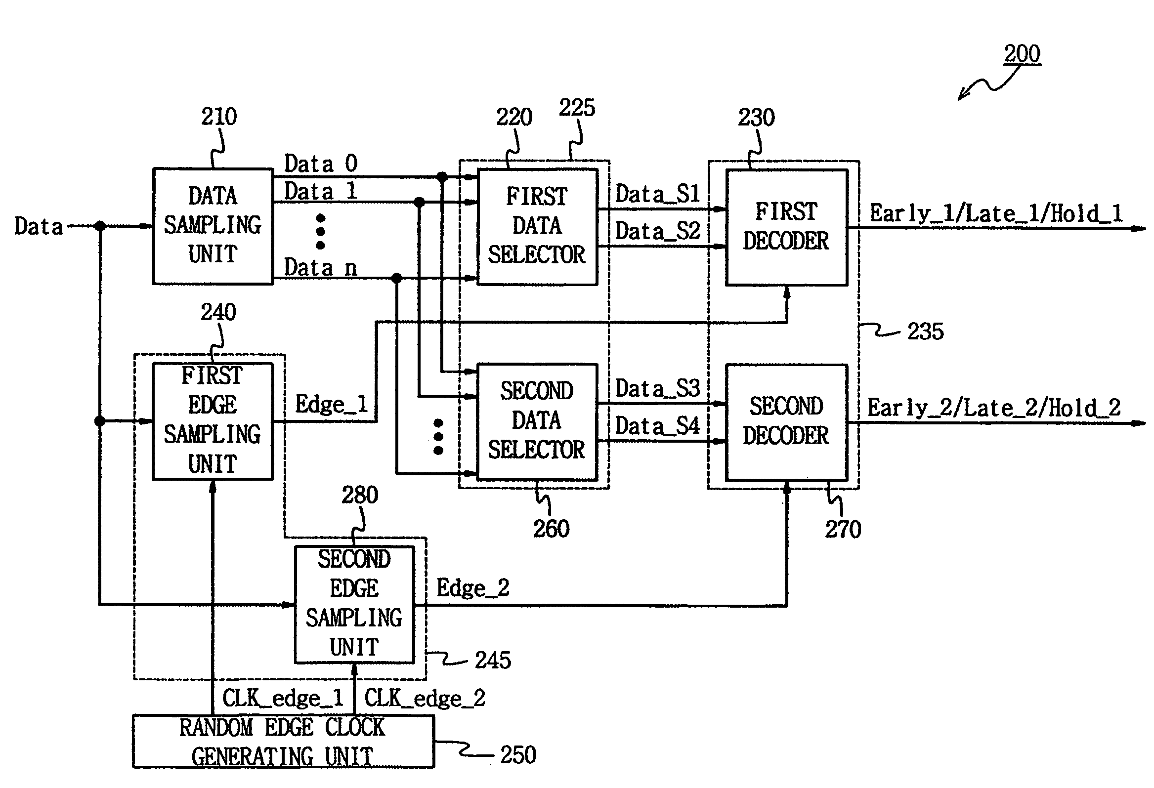
[0051]FIG. 6 is a block diagram of a CDR circuit according to an exemplary d...


PUM


Abstract

A clock and data recovery (CDR) circuit comprises a data sampling unit which latches serial data input in response to data clock signals, and outputs a plurality of sampling data, the data clock signals maintaining a constant phase difference and having mutually different phases, an edge sampling unit which outputs an edge sampling signal generated by sampling edge information of the serial data in response to a selection edge clock signal, the selection edge clock signal being randomly selected from among a plurality of edge clock signals, a data selection unit which selects at least two consecutive sampling data from among the plurality of sampling data, and a decoding unit which performs a logical operation of the sampling data selected by the data selection unit and the edge sampling signal.

Description

BACKGROUND AND SUMMARY[0001]1. Field of the Invention[0002]The present disclosure relates to a clock and data recovery circuit and a method of recovering clock and data from a received signal and, more particularly, to circuits and methods of clock and data recovery which perform random edge sampling every predetermined number of data periods.[0003]A claim of priority is made under 35 U.S.C. §119 from Korean Patent Application 10-2006-0122267, filed on Dec. 5, 2006, the contents of which are hereby incorporated by reference in their entirety.[0004]2. Description of the Related Art[0005]Two types of communication methods are predominantly used in the communication industry. These two communication methods are serial communications and parallel communications. Serial communication methods use serial interface devices to conduct serial communication. Similarly, parallel communication methods use parallel interface devices to conduct parallel communication. In general, a serial interfac...

Claims


Application Information

Patent Timeline
Patent Type & Authority Patents(United States)
IPC IPC(8): H04L7/00
CPCH04L7/0337H03K5/12
Inventor BAE, SEUNG-JUN
Owner SAMSUNG ELECTRONICS CO LTD
Why Eureka
Try Eureka