
Modulation and demodulation apparatuses and methods for wired/wireless communication system

a technology of wired/wireless communication and demodulation apparatus, applied in the field of wired/wireless communication system demodulation apparatus and methods, can solve the problems of difficult and complicated realization, inability to guarantee a communication speed of 10 mb/s or higher, and inability to use turbo equalizer-based methods, etc., to achieve high transmission power efficiency

Inactive Publication Date: 2011-06-14
ELECTRONICS & TELECOMM RES INST
View PDF10 Cites 9 Cited by
  • Summary
  • Abstract
  • Description
  • Claims
  • Application Information

AI Technical Summary

Benefits of technology

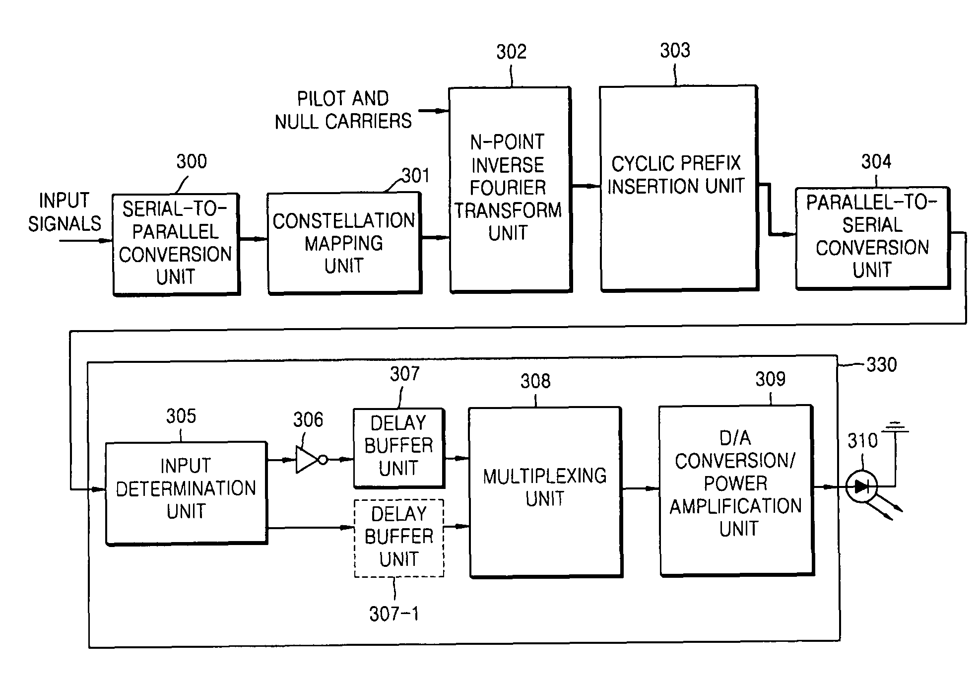
The present invention provides apparatuses and methods for wired / wireless optical signal modulation and demodulation using an intensity modulation (IM) / direct detection (DD) method and an orthogonal frequency division multiplexing (OFDM) method. The invention addresses the low transmission power efficiency and high peak-to-average power ratio (PAPR) of conventional OFDM symbols that are intensity-modulated. The invention provides a modulation apparatus that determines the polarity of each pulse on a bipolar OFDM symbol frame and generates positive and negative sub-frames, delays the sub-frames, converts the delayed sub-frames to analog unipolar OFDM symbol frames, amplifies the frames, and demodulates them using a low noise amplification unit, an A / D conversion unit, a time-domain equalization unit, a demultiplexing unit, a delay buffer unit, a polarity restoration unit, and an addition unit. The invention also provides a unipolar OFDM symbol frame that guarantees high transmission power efficiency.

Problems solved by technology

However, in an indoor environment where multiple paths may exist, TD modulation methods cannot guarantee a communication speed of 10 Mb / s or higher without the aid of signal interference compensation equipment such as equalizers.
However, the turbo equalizer-based method requires a considerable amount of computation, and is difficult and complicated to realize.
However, the OFDM method is likely to lower the operating efficiency of power amplifiers because the peak-to-average power ratio (PAPR) of output waveforms is extremely high.
In addition, the OFDM method is likely to deteriorate the performance of communication because of a high possibility of signal distortion due to non-linearity of power amplifiers.
In other words, according to conventional IM methods, IM output signals with a high PAPR can be interpreted as very low signal transmission power efficiency.
Therefore, MSM and OFDM method using a considerable number of sub-carriers may not be suitable for IM-based optical signal modulation, even though it has excellent multiple path characteristics.
However, when N is too large, it is very difficult to realize a large-scale block coder which is capable of operating in real time to minimize PAPR.
The aforementioned all disclosed methods to minimize PAPR still have a problem in that the waste of a DC bias power cannot be completely prevented because of the bipolar features of OFDM signals.

Method used


Image

  • Modulation and demodulation apparatuses and methods for wired/wireless communication system
  • Modulation and demodulation apparatuses and methods for wired/wireless communication system
  • Modulation and demodulation apparatuses and methods for wired/wireless communication system

Examples


Embodiment Construction

[0045]The present invention will now be described more fully with reference to the accompanying drawings in which exemplary embodiments of the invention are shown.

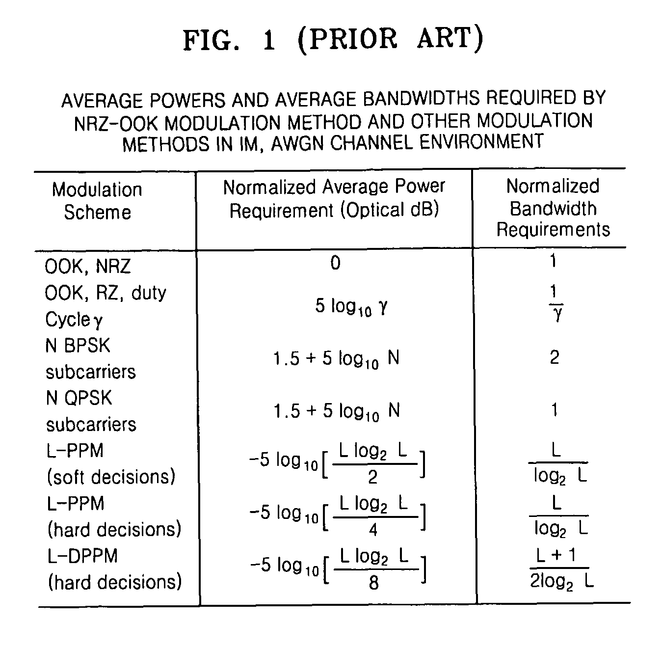
[0046]FIG. 1 is a table presenting the average powers and bandwidths required by a non-return-to-zero (NRZ) on-off keying (OOK) method and other modulation methods in an intensity modulation (IM), additive white Gaussian noise (AWGN) channel environment. FIG. 1 says that all the known MSM has a poor transmission power efficiency for IM

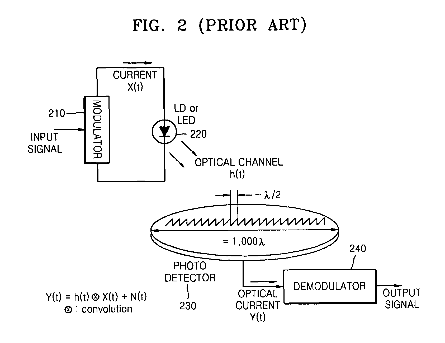
[0047]FIG. 2 is a diagram illustrating a conventional IM / DD. Referring to FIG. 2, an input signal includes data to be transmitted, and a modulator 210 converts the input signal into line code which is suitable for a given channel, amplifies the line code to a current suitable for driving a laser diode (LD) / light-emitting diode (LED) 220, and outputs the current.

[0048]A received optical signal is converted into an electric signal by a photo detector 230 such as an avalanche photodiode (APD) or...


PUM


Abstract

Wired / wireless optical signal modulation and demodulation apparatuses and methods using an intensity modulation / direct detection method and an orthogonal frequency division multiplexing (OFDM) method are provided. A unipolar OFDM symbol frame is generated by determining the polarity of each of a plurality of sub-frames of a bipolar OFDM symbol frame which comprises both a plurality of positive pulses and a plurality of negative pulses, inverting the polarity of the sub-frames which are determined to be negative, delaying one of the positive sub-frame and a positive sub-frame obtained through the inversion by the duration of the sub-frames, and multiplexing the result of the delaying and whichever of the positive sub-frame and the positive sub-frame obtained through the inversion is not the result of the delaying. The unipolar OFDM symbol frame can guarantee high power amplification efficiency and high transmission power efficiency, and is robust against a multi-path channel environment. Therefore, the unipolar OFDM symbol frame can be used in various optical signal modulation / demodulation methods for wireless indoor broadband optical transmission devices, wired broadband optical transmission devices using multi-mode optical fibers, and radio-over-fiber devices which transmit baseband analog signals as optical signals.

Description

[0001]The present patent application is a non-provisional of International Application No. PCT / KR2006 / 005140, filed Nov. 30, 2006.CROSS-REFERENCE TO RELATED PATENT APPLICATION[0002]This application claims the benefit of Korean Patent Application No. 10-2005-0116582, filed on Dec. 1, 2005, in the Korean Intellectual Property Office, the disclosure of which is incorporated herein in its entirety by reference.BACKGROUND OF THE INVENTION[0003]1. Field of the Invention[0004]The present invention relates to modulation and demodulation apparatuses and methods which are capable of guaranteeing high transmission power efficiency to wired / wireless optical communication apparatuses with an orthogonal frequency division modulation (OFDM) method and an intensity modulation (IM) / direct detection (DD) method.[0005]2. Description of the Related Art[0006]Traditionally, in optical telecommunications fields, where it is very difficult to realize coherent communication systems, IM / DD methods have been ...

Claims


Application Information

Patent Timeline
Patent Type & Authority Patents(United States)
IPC IPC(8): H04K1/10H04L27/28
CPCH04L27/2608Y02B60/50H04L27/2626H04L5/0044H04B10/2575H04L27/01H04L27/2656Y02D30/70H04L27/2602
Inventor JUN, YONG IL
Owner ELECTRONICS & TELECOMM RES INST
Learn More