Atomisation of a precursor into an excitation medium for coating a remote substrate

a technology of excitation medium and precursor, which is applied in the direction of coating, metal material coating process, plasma technique, etc., can solve the problems of ion etching effect, and reducing the deposition rate, so as to reduce the effect of the exciting medium

Inactive Publication Date: 2011-06-28
SURFACE INNOVATIONS LTD
View PDF35 Cites 24 Cited by
  • Summary
  • Abstract
  • Description
  • Claims
  • Application Information

AI Technical Summary

Benefits of technology

[0011]This method avoids excessive damage to the substrate or coating applied thereto from occurring.
[0035]The coating formed can be such as to improve the hydrophobic and / or oleophobic, adhesive, gas barrier, moisture barrier, release, electrical and thermal conductivity, dielectric, optical, biomedical, biotechnological and tribological properties of the substrate.
[0040]In a further aspect of the invention there is provided a method for depositing a coating, comprising a source of atomised or nebulized coating forming material (such as an organic or organo-silicon monomer or oligomer) which is introduced into an exciting medium that facilitates the formation of activated precursor species to the coating (such as monomer radicals, ions or oligomers), which precursor species are subsequently deposited onto a substrate, situated outside of the exciting medium, forming the coating.
[0041]The remote placement of the substrate prevents the high energy species that constitute the exciting medium from causing excessive damage to the substrate and the growing coating.
[0055]Typically control means are provided for the coating material introduction means, exciting medium generating means and position of the substrate to ensure that the same are adjusted and set to suit particular operating conditions and to remove or minimise any effect of the exciting medium on the substrate.

Problems solved by technology

However, deleterious effects of high energy species can be present within the “exciting medium”, such as bombarding ions and UV photons.
This can prevent the coating of sensitive substrates with films that retain a significant degree of monomer functionality and can also cause ion etching effects.
However in both cases the coating is achieved through the introduction of gaseous materials and this slows the deposition rate significantly and renders the same commercially unviable for many applications.

Method used


Image

  • Atomisation of a precursor into an excitation medium for coating a remote substrate
  • Atomisation of a precursor into an excitation medium for coating a remote substrate
  • Atomisation of a precursor into an excitation medium for coating a remote substrate

Examples


example 1

Deposition of Hydrophobic / oleophobic Films

[0072]1H, 1H, 2H, 2H perfluorooctylacrylate is placed into a monomer 12 tube having been purified using repeated freeze-pump-thaw cycles. Coating deposition experiments are performed in an apparatus consisting of an ultrasonic atomisation nozzle 4 connected to a glass vessel 16, itself comprising a radiofrequency plasma excitation generating means 17 and exciting medium volume 2, and a downstream deposition region 14 containing the substrate 6 as shown in FIG. 3. The monomer tube is connected to the ultrasonic nozzle by way of a metering valve 18. The ultrasonic nozzle is itself connected to the glass vessel by way of “nitrile” O-rings 20.

[0073]A “Pirani” pressure gauge is connected by way of a Young's tap to the glass reactor vessel. A further Young's tap is connected with the external, ambient air supply and a third leads to an Edwards E2M2 two stage rotary pump by way of a liquid nitrogen cold trap 22. All connections are grease free.

[007...

example 2

Deposition of a Hydrophilic Coating

[0081]In a second illustrative example, the method and apparatus of Example 1 and as illustrated in FIG. 3 are repeated using 2-hydroxyethyl methacrylate as the coating forming material.

[0082]The hydrophilicity of the deposited coatings are assessed by water contact angle measurements with a video capture apparatus (AST Products VCA2500XE) using sessile 2 uL droplets of deionised water. Information on the chemical groups present within the films was obtained using FT-IR (Perkin Elmer, Spectrum One).

[0083]The water contact angle of coatings deposited onto polished silicon wafers was 28±2°, confirming that they are indeed hydrophilic.

[0084]FIG. 4 compares the infrared spectrum of the starting material, 21 with that of a film deposited onto a polished silicon wafer 23. Absorption bands indicative of the carbon-carbon double bond in the monomer are absent in the coating. In contrast, the sought hydroxyl group is shown to be present in both. These resul...

example 3

Deposition Using a Remote Microwave Frequency Excitation Source

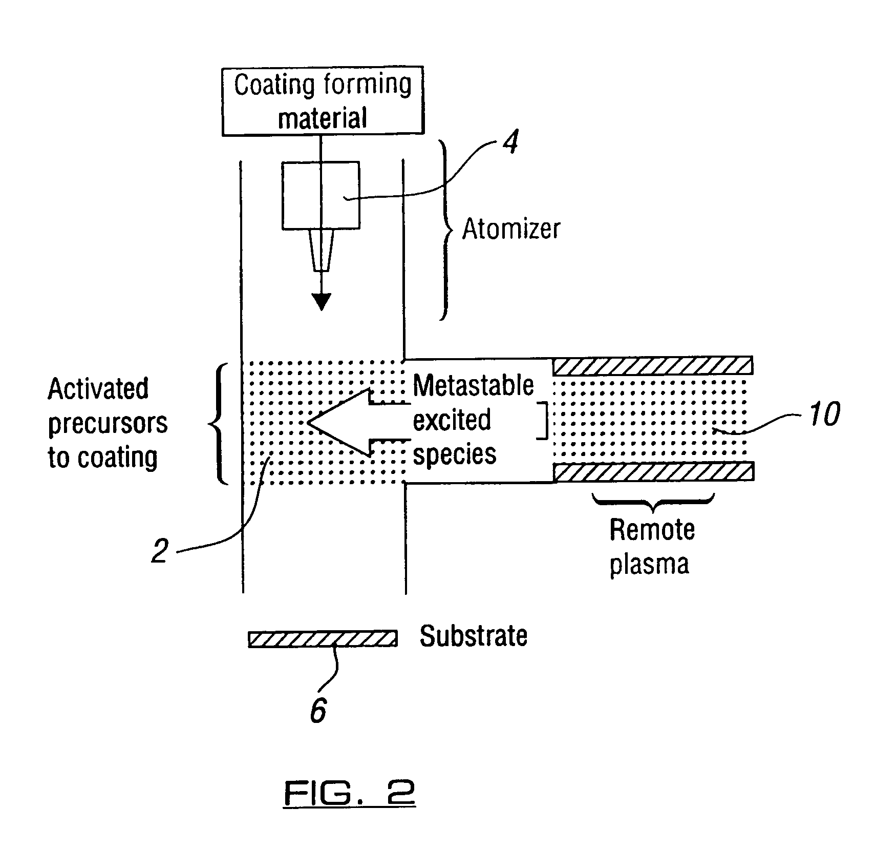
[0085]In a third illustrative example of the method, described with reference to FIG. 5, coatings are deposited using an apparatus consisting of an ultrasonic atomising nozzle 4 and a remote microwave plasma source 24 for generating the exciting medium 2. Activation of the coating forming material 25 is achieved by directing its atomised spray as indicated by arrow 27 into the output of the remote microwave plasma, that being the exciting medium 2. The activated coating precursor species are then allowed to deposit onto the substrate 6 remote from the exciting medium. The substrate is disposed in a manner that precludes the direct exposure to species incident from the plasma as shown in FIG. 5 in this case by means of the distance 8 and the bend 26.

[0086]The apparatus is temperature controlled (20-150° C.) and evacuated using an E2M28 two stage Edwards rotary pump by way of a liquid nitrogen cold trap 22.

[0087]The remote...


PUM

PropertyMeasurementUnit
pressureaaaaaaaaaa
pressureaaaaaaaaaa
pressureaaaaaaaaaa

Abstract

The invention relates to a method and apparatus for applying and forming a coating on a substrate surface by the application of at least one atomized coating forming material onto the substrate to form the coating. The atomized coating forming material, upon leaving a suitable atomizer which can be an ultrasonic nozzle or nebulizer for example, passes through an exciting medium and, upon leaving the exciting medium, passes to the substrate. The substrate is positioned remotely from the exciting medium.

Description

CROSS-REFERENCE TO RELATED APPLICATIONS[0001]This application is a National Phase of International Application No. PCT / GB2003 / 002140 filed on May 16, 2003, which claims priority to GB 0211354.6 filed on May 17, 2002.BACKGROUND OF THE INVENTION[0002]The invention to which this application relates is to the application of a coating to a substrate involving the improved utilisation of an exciting medium.[0003]The use of excitation mediums is known in the application of coatings. However, deleterious effects of high energy species can be present within the “exciting medium”, such as bombarding ions and UV photons. This can prevent the coating of sensitive substrates with films that retain a significant degree of monomer functionality and can also cause ion etching effects.[0004]The exciting medium tends to be the medium in which, conventionally, the substrate to be coated is positioned. The exciting medium can be generated in a number of ways, the most common of which is the generation ...

Claims


Application Information

Patent Timeline
Patent Type & Authority Patents(United States)
IPC IPC(8): H05H1/24B05D7/24C23C16/448C23C16/452
CPCB05D1/62C23C16/452C23C16/4486
Inventor WARD, LUKE JOHN
Owner SURFACE INNOVATIONS LTD
Why Eureka
Try Eureka