Power source apparatus

a power source and power supply technology, applied in lighting and heating apparatus, cell components, cell component details, etc., can solve the problems of difficult handling of cooling medium and lower thermal conductivity of cooling medium, and achieve the effect of preventing temperature variations of cooling liquid, preventing temperature variations, and simplifying structur

Inactive Publication Date: 2011-07-05
TOYOTA JIDOSHA KK
View PDF22 Cites 13 Cited by
  • Summary
  • Abstract
  • Description
  • Claims
  • Application Information

AI Technical Summary

Benefits of technology

[0026]According to the present invention, since the laminar flow of the cooling liquid that has at least substantially the same width as the length of the power source elements flows within the case, it is possible to prevent variations in temperature of the cooling liquid for the power source module including the plurality of power source elements preferably.
[0027]In addition, since the fan forming the laminar flow is placed in the case such that the fan is immersed in the cooling liquid together with the power source module, it is possible to prevent variations in temperature of the cooling liquid preferably with a simplified structure.

Problems solved by technology

However, the thermal conductivity of the cooling medium is lower than that in the liquid cooling.
On the other hand, in the liquid cooling, the cooling medium is difficult to handle.

Method used


Image

  • Power source apparatus
  • Power source apparatus
  • Power source apparatus

Examples


embodiment 1

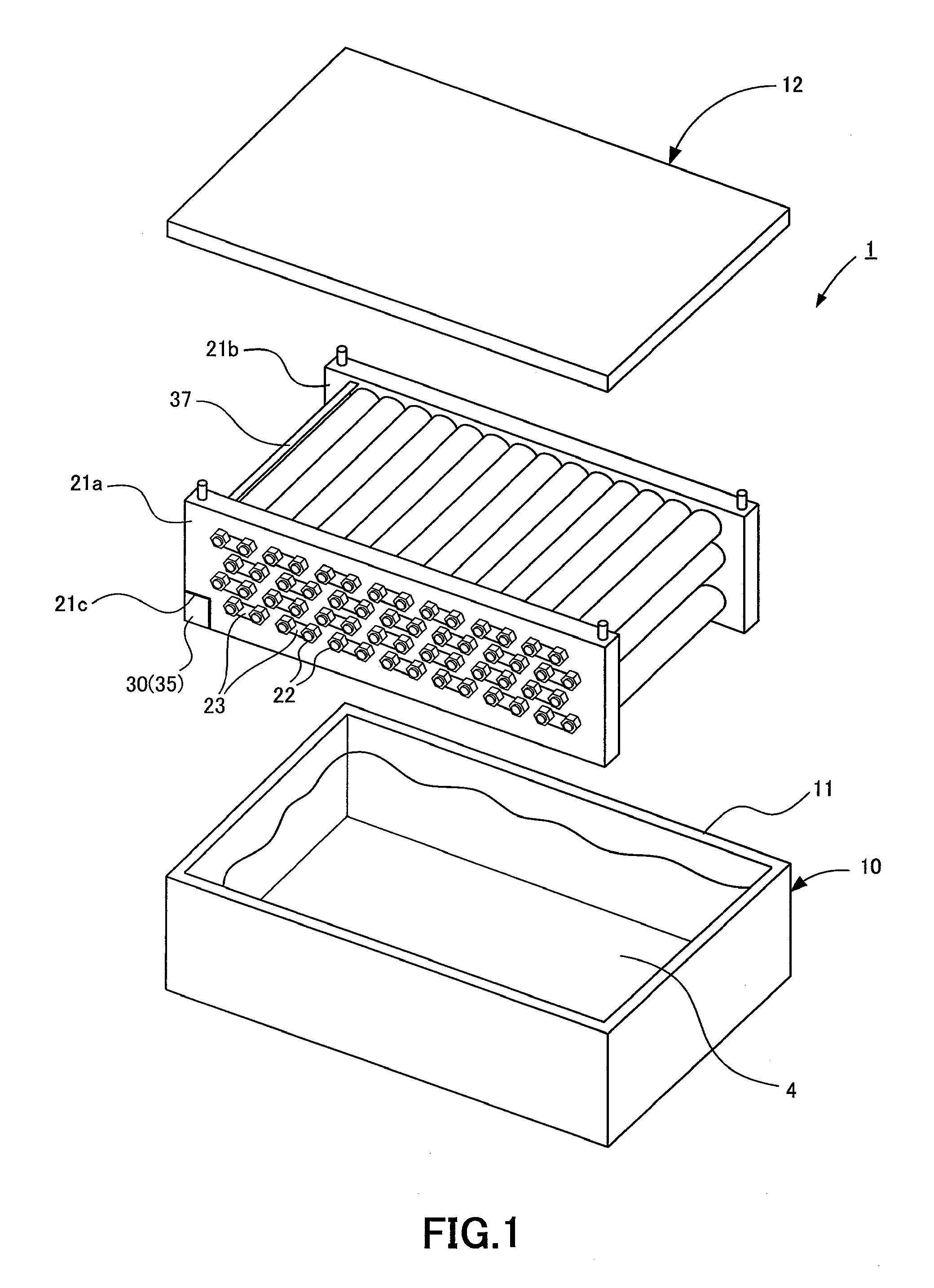
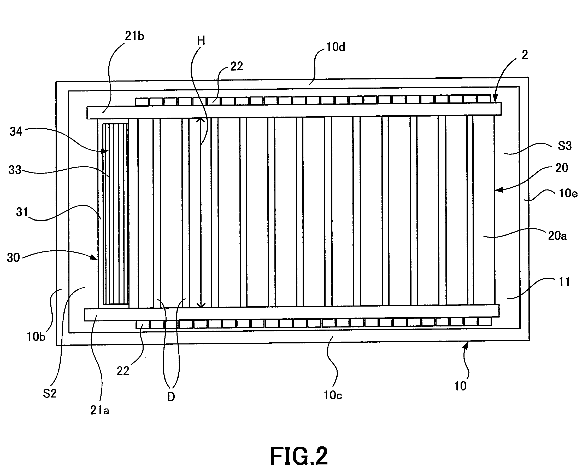
[0040]A power source apparatus in Embodiment 1 of the present invention will be described with reference to FIGS. 1 to 4. FIG. 1 is an exploded perspective view showing a power source apparatus 1 of Embodiment 1. FIG. 2 is a top view showing the power source apparatus 1 of Embodiment 1. FIG. 3 is a schematic diagram showing the outer appearance of a cross flow fan which forms a laminar flow in the power source apparatus 1 of Embodiment 1. FIG. 4 is a side view showing the cross flow fan of the power source apparatus 1.

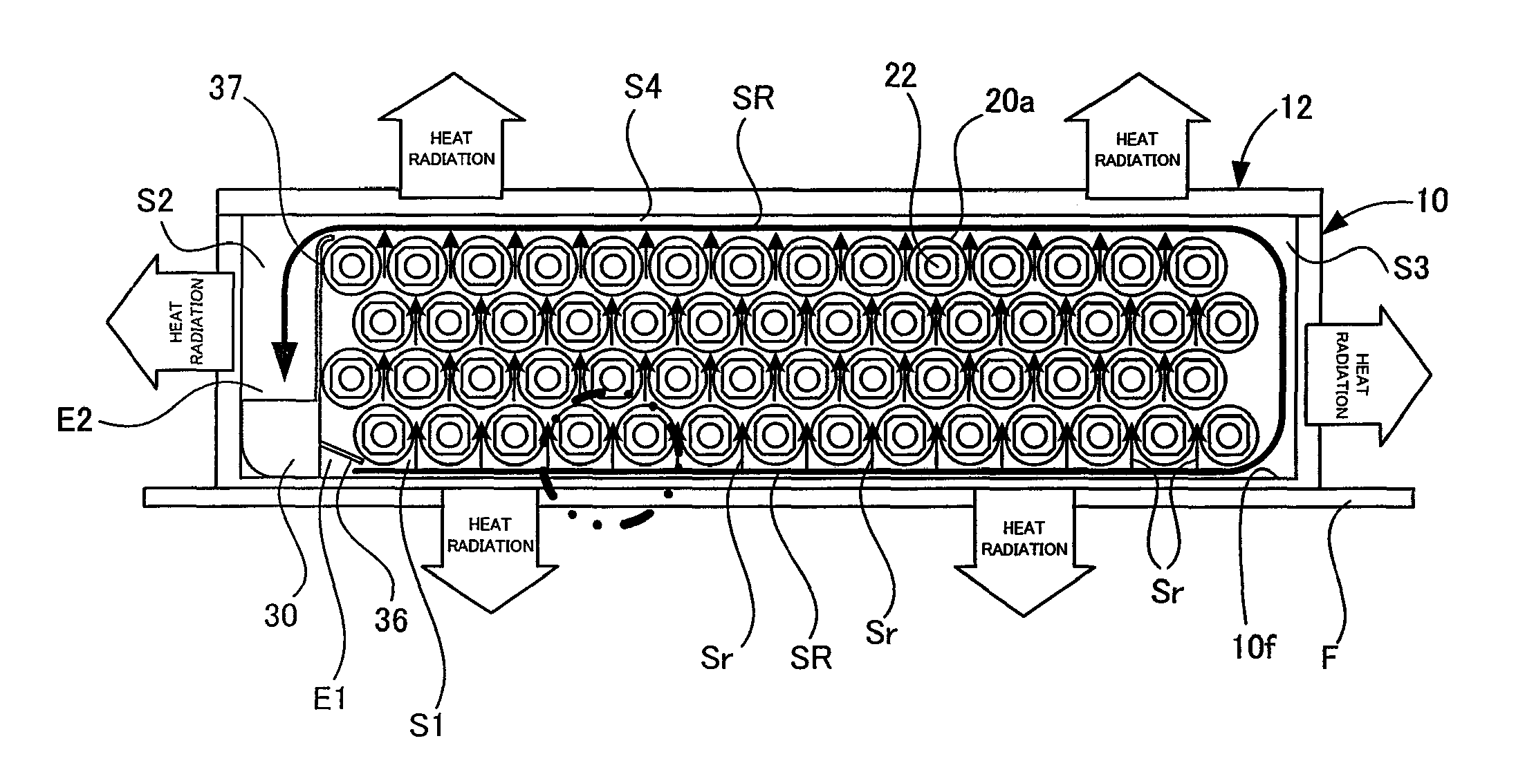
[0041]The power source apparatus 1 of Embodiment 1 is formed of a battery unit 2 which serves as a power source module, later described, and a case member which includes a lower case 10 having an opening portion 11 and putting the battery unit 2 in and an upper case 12 covering the opening portion 11 of the lower case 10. The lower case 10 and the upper case 12 provide sealed space for housing the battery unit 2. The sealed space is filled with a cooling liquid 4 for u...

embodiment 2

[0077]A power source apparatus in Embodiment 2 of the present invention will be described with reference to FIGS. 9 and 10. FIG. 9 is an exploded perspective view showing a power source apparatus 1a of Embodiment 2. FIG. 10 is a section view showing the power source apparatus 1a in Embodiment 2 of the present invention to explain the flow of a cooling liquid.

[0078]In Embodiment 2, a flow directing portion 40 is provided at a bottom portion of a lower case 10 forming part of a case member as described in Embodiment 1 to direct at least part of a laminar flow of a cooling liquid 4, that is, a branch laminar flow Sr as described in Embodiment 1 between cells 20a. Other structures are identical to those in Embodiment 1, so that they are designated with the same reference numerals as in Embodiment 1 and description thereof is omitted.

[0079]As shown in FIG. 9, the flow directing portion 40 has a plurality of protruding portions 41a which protrude in a direction substantially perpendicular...


PUM

PropertyMeasurementUnit
lengthaaaaaaaaaa
distanceaaaaaaaaaa
heightaaaaaaaaaa

Abstract

A power source apparatus includes a power source module which is formed of a plurality of power source elements, a case which houses the power source module and a cooling liquid, a fan which is placed in the case in a state in which the fan is immersed in the cooling liquid together with the power source module, the fan forming a laminar flow of the cooling liquid, the laminar flow having a width at least substantially the same as a length of the power source element in a length direction of the power source element.

Description

[0001]This is a 371 national phase application of PCT / JP2008 / 061829 filed 30 Jun. 2008, claiming priority to Japanese Patent Application No. 2007-177444 filed 5 Jul. 2007, the contents of which are incorporated herein by reference.TECHNICAL FIELD[0002]The present invention relates to a power source apparatus, and more particularly, to cooling control of the power source apparatus.BACKGROUND ART[0003]A power source element (power storage element) such as a battery cell and a capacitor within a power source apparatus generates heat during charge and discharge. A cooling apparatus (cooling mechanism) provided for the power source apparatus is used to cool the power source element to control the temperature of the whole power source apparatus, thereby achieving stabilization of the power source element, long life thereof, and stabilization of power supply.[0004]Methods of cooling the power source apparatus (power source element) include gas cooling and liquid cooling. Heat from the powe...

Claims


Application Information

Patent Timeline
Patent Type & Authority Patents(United States)
IPC IPC(8): H05K7/20H01M2/12H01M10/60H01M10/613H01M10/617H01M10/625H01M10/643H01M10/6551H01M10/6556H01M10/6557H01M10/6567H01M10/6568H01M50/209H01M50/213
CPCH01M2/1077H01M10/5004H01M10/5075H01M8/04029H01M10/503H01M10/5046H01M10/5016H01M10/625H01M10/6551H01M10/6567H01M10/643H01M10/613Y02E60/50Y02E60/10H01M50/209H01M50/213
Inventor MURATA, TAKASHI
Owner TOYOTA JIDOSHA KK
Why Eureka
Try Eureka