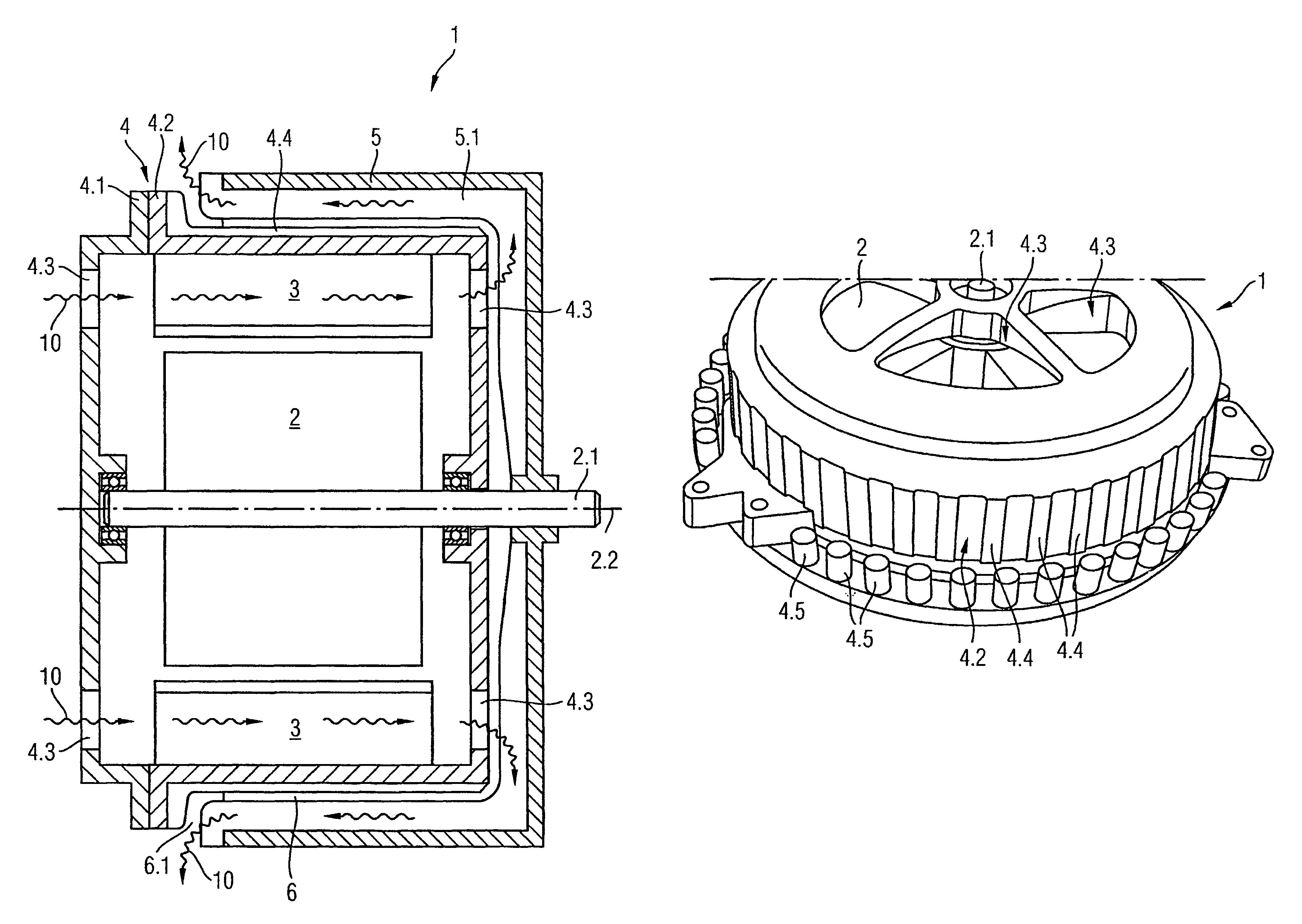
[0014]The invention is based on the principle of improving the cooling of an electromotor by also using the motor housing encasing the electromotor as a
heat sink to dissipate the lost heat from the winding to a cooling air flow. To do this, the cooling air flow is directed through the motor housing and in an air gap between a ventilator vessel and along the exterior of the motor housing.
[0015]According to an embodiment, the electromotor has a rotating internal rotor and a fixed, electromagnetically excited external
stator with a winding. As opposed to an electromotor with a permanently excited external stator, here the lost heat from the winding and the electromagnetically charged iron material is dissipated outwards directly to the motor housing, which is connected with the external stator in a heat-conductive manner.
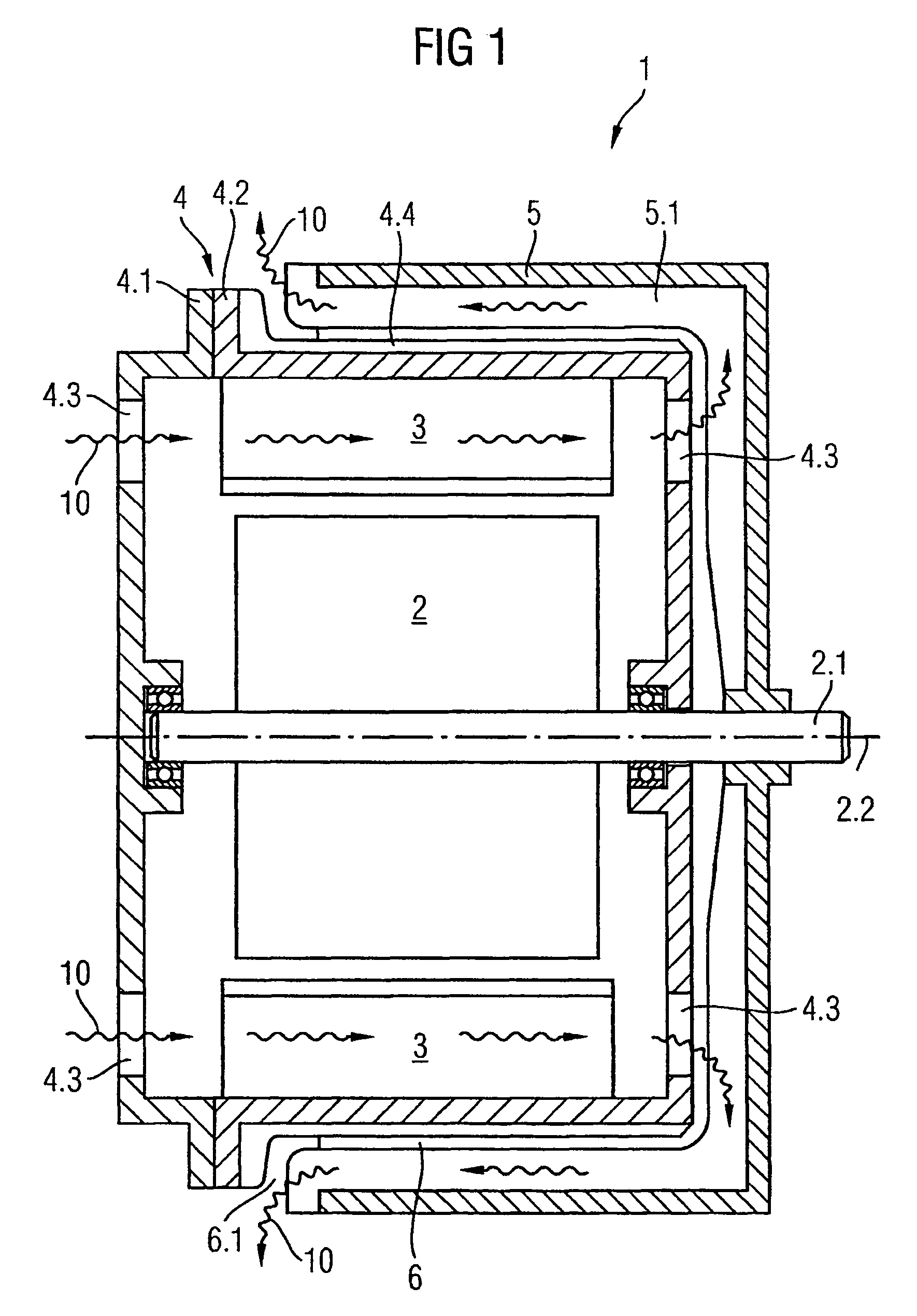
[0007]The task of the invention is to improve the cooling of an electromotor and thus to increase its thermal robustness. According to an embodiment, an electromotor may comprise a rotor rotatably mounted on a rotor axle and a fixed stator in the inside of a motor housing and a ventilator vessel, wherein the ventilator vessel is fixably or in torque proof fashion connected with the rotor and at least partially encompasses the motor housing in the shape of a pot, in such a way that an air gap with an air gap opening is formed between the outer wall of the motor housing and the wall of the ventilator vessel, wherein the motor housing has ventilation openings both outside and inside the air gap and the ventilator vessel has moldings, which act as air blades and are arranged in such a way that when the rotor is turning, a difference in pressure is formed between the ventilation opening arranged outside the air gap and the air gap opening, which generates an air flow, wherein the stator is an electromagnetically excited external stator, which has electromagnetically active iron material and a winding and which is fixably or in torque proof fashion connected to and in
heat conducting connection with the outside wall of the motor housing and wherein in the inside of the motor housing the air flow flows directly past the stator and in the air gap past the exterior of the outside wall of the motor housing and takes up lost heat from the external stator in each case.
[0019]Thereby, the cooling of the external stator, thus of the winding and the electromagnetically active iron material of the electromotor, comprises, according to an embodiment, both the case that the cooling air flow takes up a part of the lost heat generated when it flows through the inside of the motor housing, and the case that, at the exterior of the motor housing, the cooling air flow takes up another part of the lost heat generated and dissipates it into the environment.
[0020]The dissipation of lost heat from the thermally loaded winding is thus significantly improved compared with a conventional electromotor. The improved cooling of the electromotors makes it possible to keep the same performance and have a smaller installation space requirement or to keep the same installation space requirement and have a higher performance. At the same the electromotor is guaranteed a long service life. Breakdowns of the electromotor due to overheating are avoided.
[0008]This invention is described below with reference to an exemplary embodiment, which is explained in more detail with the aid of
schematic drawings, in which;
[0021]According to an embodiment, the moldings, which increase the heat transferring surfaces of the motor housing, can be arranged inside the air gap between the ventilator vessel wall and the motor housing and / or in the areas bordering the air gap on the exterior of the motor housing. The cooling air flow passes over these moldings, in particular cooling fins or cooling pegs, and they serve as cooling elements. At the same time these cooling elements also help to create a swirl in the cooling air flow, as the ventilator vessel rotates relative to the fixed housing part on the output side. This arrangement allows even more
waste heat to be picked up and dissipated as the cooling air flow passes through the circumferential air gap and / or as the air flow enters or exits into or out of the air gap opening. This further increases the thermal robustness of the electromotor.
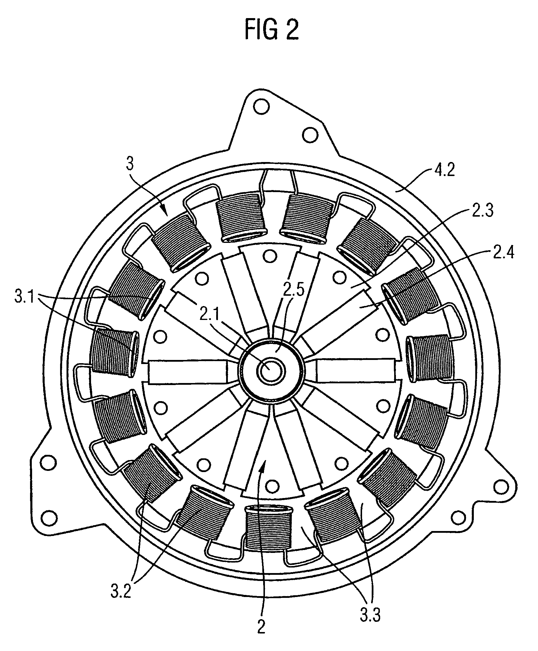
[0022]Further advantages can be achieved by the fact that individual stator teeth of the external stator are wound in a
single tooth winding pattern, according to an embodiment. Thereby the stator teeth arranged radially inwards on the external stator are each covered by a coil, whereby the wire windings of the coils are arranged in the slots disposed between the stator teeth. As the slots, for manufacturing reasons, cannot be completely filled with wire windings anyway, slot slits remain open between the individual stator teeth, according to an embodiment. The
advantage of this type of winding is that no winding overhang is formed on the face covering the slots and thus the slot slits are open on both faces of the stator. This allows the cooling air flow an almost unhindered passage through the slot slits, in direct contact and in axial direction along the wire windings of the winding. Thereby the cooling air flow takes up the lost heat generated in the current-carrying wire windings. This measure increases the surface within the motor housing over which flows the cooling air flow. Moreover, the almost unhindered flow of the cooling air flow through the slot slits allows an increase in the
air mass flow. Both features increase the dissipation of lost heat to the cooling air flow and thus also increase the thermal robustness.
[0023]According to a further embodiment, the electromotor may have a permanent
magnet excited internal rotor. Such a rotor has itself the characteristic of generating almost no lost heat. This has the
advantage that the cooling air flow in the inside of the motor housing is not burdened with additional heat and can be used to the full to take up lost heat from the wound external stator. Furthermore, according to an embodiment, such a rotor can itself be designed to be to a great extent airtight. This forces almost the entire cooling air flow to flow past the winding of the external stator and possibly through the slot slits between the stator teeth. As a result of this the
air mass flow through the stator generating lost heat increases and hence the release of lost heat to the cooling air flow is increased and the cooling of the electromotor is improved.
[0024]According to an embodiment, through the arrangement of at least the ventilation openings of the first rear motor housing face with essentially the same radial spacing to the rotor axle as the winding, the slots or the slot slits of the stator, it is possible to achieve further advantages for the cooling of the electromotor and in particular the heat generating stator. With this arrangement of the ventilation openings, the cooling air flow entering the inside of the motor housing directly hits the winding and / or the slot slits arranged between the stator teeth. This enables the air flowing in from the environment to
stream unhindered and targeted over the heat generating stator components and this ensures an efficient dissipation of heat to the cooling air flow and contributes to increasing the
air mass flow and thus to an improved cooling.
[0026]According to a further embodiment, the moldings of the ventilator vessel, which act as air blades, can be arranged in radial and / or axial direction, straight or curved on the inside of the ventilator vessel and be fitted to the contour of the motor housing with minimum spacing. Hereby the effect that generates the air
pressure difference is increased. Thus, the air in the air gap is captured as completely as possible by the air blades and accelerated in a
peripheral direction. At the same time, the
centrifugal force accelerates the air in radial direction away from the motor axle. Because the air blades are arranged curved in radial direction on the ventilator vessel floor like the air blades of a radial blower, additional air pressure differences are formed on the ventilator blades, which accelerate the air flow further. By this means the air
pressure difference as a whole is increased and hence the air
mass flow, which in turn results in improved cooling of the electromotor.
[0024]According to an embodiment, through the arrangement of at least the ventilation openings of the first rear motor housing face with essentially the same radial spacing to the rotor axle as the winding, the slots or the slot slits of the stator, it is possible to achieve further advantages for the cooling of the electromotor and in particular the heat generating stator. With this arrangement of the ventilation openings, the cooling air flow entering the inside of the motor housing directly hits the winding and / or the slot slits arranged between the stator teeth. This enables the air flowing in from the environment to
stream unhindered and targeted over the heat generating stator components and this ensures an efficient dissipation of heat to the cooling air flow and contributes to increasing the air
mass flow and thus to an improved cooling.


