Pulley for a power transmission member, a separate starter-alternator fitted with such a pulley, and an engine drive system

a technology of power transmission and pulley, which is applied in the direction of motors, rotating vibration suppression, portability lifting, etc., can solve the problems of poor drive (slip), poor noise, and large variations in tension, so as to reduce the risk of generating tension, and reduce the effect of decoupling

Inactive Publication Date: 2011-07-26
HUTCHINSON SA
View PDF19 Cites 40 Cited by
  • Summary
  • Abstract
  • Description
  • Claims
  • Application Information

AI Technical Summary

Benefits of technology

[0016]The invention seeks to solve the above-mentioned problems and in particular to provide a system that is capable, while starting, of filtering the torque jolts and of limiting variations in tension, and also limiting the risk of generating tension that is too low giving rise to slip and to noise, while also providing effective decoupling while running.
[0018]More precisely, the invention provides a pulley for a member for transmitting power by means of a belt at a starting speed and then at a started speed, the pulley including at least one resilient decoupling element located between a central hub and a rim over which the drive belt is tensioned, and in which the resilient element is associated with a progressive deflection limiter element to form a resilient decoupling assembly that provides stiffnesses that are adapted to filtering and damping transmission both while starting and while running.
[0021]The resilient ring is made of a rubber type material, and preferably: silicone, a hydrogenated nitryl butadiene rubber (HNBR), chloroprene, an etheylene propylene diene monomer (EPDM), a butadiene rubber (BR), a nitrile rubber (NR), or a combination of at least two of these compounds. The decoupler element may also be a torsion spring having a steel blade or a helical steel spring. This diversity of materials makes it possible to adapt stiffness to any transmission system.
[0040]In particular applications, at least one above-described deflection limiter may be designed to present stiffness that is sufficient on its own, i.e. without a decoupling element or without a declutched decoupling element, to provide effective damping while starting and sufficient decoupling while running.

Problems solved by technology

Unfortunately, starting an engine involves dynamic phenomena that are violent and that fluctuate rapidly as a function of internal friction varying depending on the positions of the connecting rods and on successive cylinders being put into compression.
Since inertia in the starter-alternator is high, the dynamic torque generated thereby is of large amplitude, and alternates between being positive and negative in spite of rotation taking place in one direction only: this torque leads to large variations in tension, with high tension levels stressing the components (belts, tensioners, winders), and with low tensions leading to poor drive (slip) and to noise.
Unfortunately, a conventional decoupling pulley mounted on an alternator is not capable of delivering driving torque greater than a value that is typically about 30 N.m at most, which means that the crankshaft can be driven with torque of 90 N.m using a typical reduction ratio of 3 between the two members.
In particular, when torque needs to be delivered to the crankshaft at significantly higher values, torque variations are large and the resulting jolts cause slip and vibration in the transmission via the belt.
In principle, freewheel or resilient freewheel systems are completely incompatible with reversible use, e.g. on a pulley of a starter-alternator for driving a crankshaft, because of the change of direction in the torque.

Method used


Image

  • Pulley for a power transmission member, a separate starter-alternator fitted with such a pulley, and an engine drive system
  • Pulley for a power transmission member, a separate starter-alternator fitted with such a pulley, and an engine drive system
  • Pulley for a power transmission member, a separate starter-alternator fitted with such a pulley, and an engine drive system

Examples


Embodiment Construction

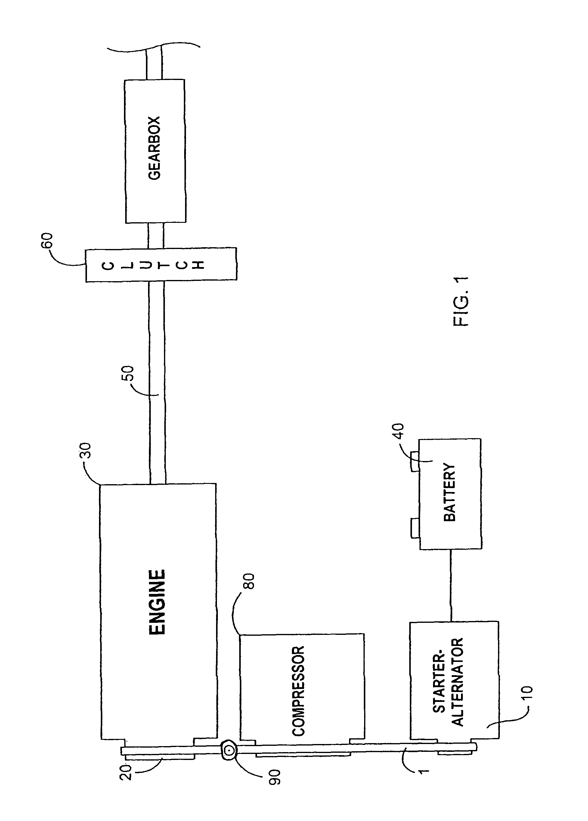
[0063]As shown diagrammatically in FIG. 1, a separate starter-alternator 10 is located in the power unit for driving the wheels of a motor vehicle by being coupled to the crankshaft 20 of the engine 30 via a drive belt 1. The alternator 10 is also electrically connected to the battery 40. The engine 30 drives the driving wheels via a transmission shaft 50 whose driving torque is controlled by a clutch 60, with the clutch being coupled to a gearbox 70.

[0064]The belt also generally drives an air conditioning compressor 80 when it is engaged. A tensioner 90 serves to keep the belt 1 under tension. The pulley of the invention is used on the alternator and on the crankshaft, and advantageously on the compressor.

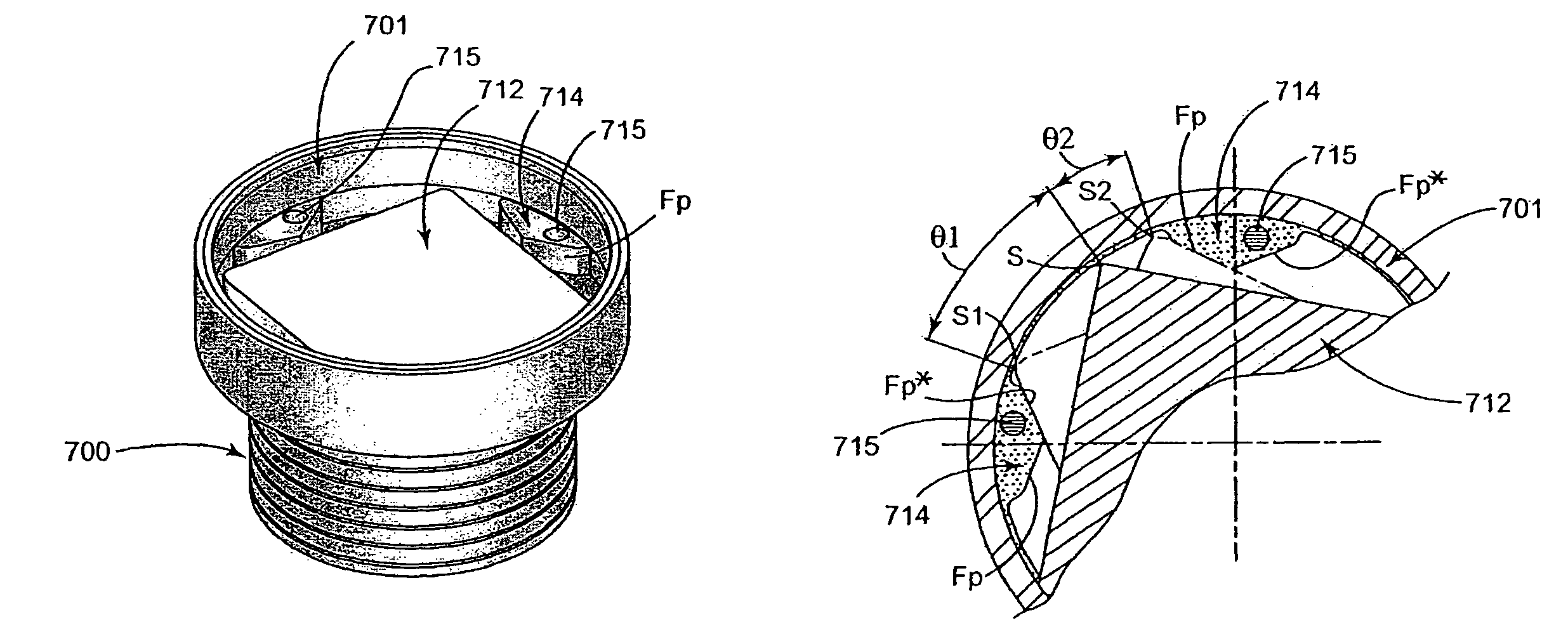
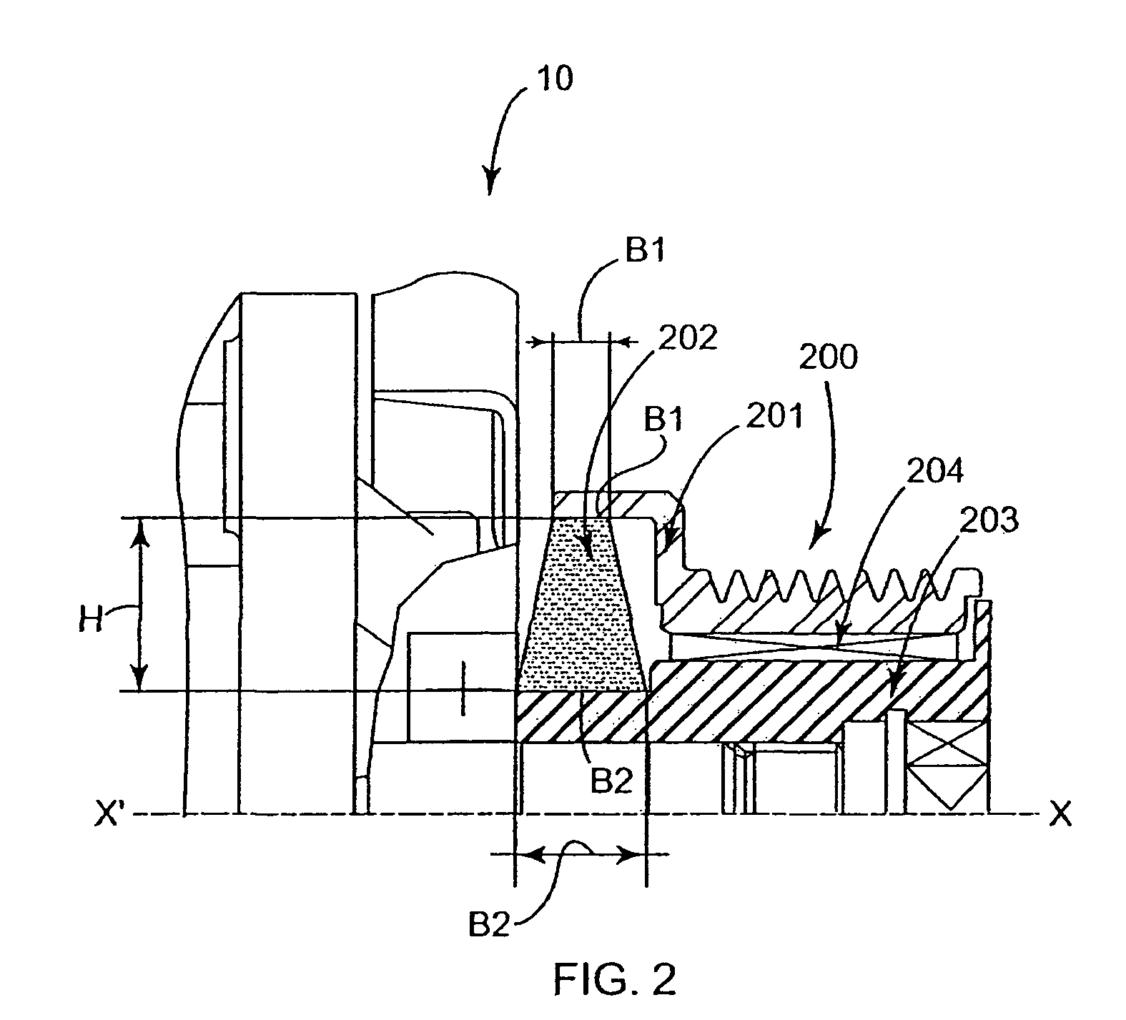
[0065]FIG. 2 is a section view, simplified by omitting the symmetrical portion about the axis X′X, showing a first embodiment of a pulley 200 of the invention having an annular ring of rubber material for use with a separate reversible alternator 10. The pulley 200 has a periphera...


PUM


Abstract

The invention seeks to provide a transmission system, in particular for a starter-alternator, capable both of damping large variations in torque under starting conditions (drive from the alternator) and of providing effective decoupling under running conditions (alternator driven). In an embodiment, the decoupling located between a central hub and a rim over which a drive belt (not shown) is tensioned, is provided by at least one decoupler element designed to provide optimized stiffness. In addition, the decoupler assembly is associated with at least one deflection limiter having two components: a central plate secured to an outside face of the central hub and coupled to abutments that are regularly distributed around the periphery of an inside face of the rim, the abutments and the plate being shaped so as to come into deforming contact. The resilient assembly provides two stiffness values, whether in the drive direction or in the driven direction. The invention is applicable to starter-alternators, crankshafts, and other power transmission members (compressors, etc.).

Description

[0001]The invention relates to a pulley for a power transmission member, and particularly but not exclusively for a member that is reversible, i.e. a member capable of driving and of being driven, the invention also relates to a starter-alternator that is separate from the crankshaft of an engine and that is fitted to such a pulley, and the invention also relates to a motor vehicle engine drive system that includes in particular an alternator and a crankshaft both fitted with transmission pulleys interconnected by a belt.BACKGROUND OF THE INVENTION[0002]The field in question is that of power transmission and it relates more particularly, but not exclusively, to reversible drive systems for motor vehicle engines, in particular between a crankshaft and a starter-alternator that are interconnected by a belt. Such a pulley may advantageously also be fitted to other members of the drive system, in particular members that are not reversible: a compressor, a water pump, etc.[0003]The inven...

Claims


Application Information

Patent Timeline
Patent Type & Authority Patents(United States)
IPC IPC(8): F16D3/04F16H55/32
CPCF16D3/02F16D3/12F16D3/68F16H55/36F16F15/124Y10T74/2131Y10S474/902
Inventor KAMDEM, HENRI
Owner HUTCHINSON SA
Why Eureka
Try Eureka