High efficiency eight stroke internal combustion engine

a technology of internal combustion engine and eight-stroke stroke, which is applied in the direction of machines/engines, mechanical equipment, non-fuel substance addition to fuel, etc., can solve the problems of less efficiency, low thermal efficiency of the complete cycle, and emitted more noxious chemicals, so as to increase the work output of the engine, and increase the thermal efficiency of the engine

Inactive Publication Date: 2011-08-30
JUNG PHILIP OWEN
View PDF3 Cites 14 Cited by
  • Summary
  • Abstract
  • Description
  • Claims
  • Application Information

AI Technical Summary

Benefits of technology

This invention presents an eight-stroke internal combustion engine and a method for operating the eight different strokes of this engine. A method to recover and recycle heat from the three exhaust strokes is included which increases the work output of this engine without requiring additional fuel. This invention and its included method of operation result in increased thermal efficiency of this engine. This eight-stroke engine includes a crankcase, at least one rotating crankshaft, and connecting rods, which convert the reciprocating motion of one or more pistons to the rotating motion of the crankshaft. These pistons go up and down in a cylinder equipped with valves, which allow for eight different strokes of this engine. These strokes are air or oxidizer intake, compression, combustion or power stroke one, exhaust, water or steam injection into the cylinder resulting in power stroke two, exhaust of steam, water or steam injection into the cylinder resulting in power stroke three, and the exhaust of steam. The engine, the conduits between the various parts, and the heat recovery system are well insulated in order to retain as much heat as practical. The three exhausts from this engine go to a heat recovery system where heat is recovered and is reused in subsequent strokes. This recovered heat is converted to work without the need for additional fuel. Fuels, which can be used in this engine, include hydrocarbons, hydrogen, or mixtures of each. Hydrocarbons include, but are not limited to, natural gas, reformed gas, methane, ethane, butane, propane, alcohols, gasoline, diesel, fuel oil, and coal. This process of operating an internal combustion engine with the recycling of exhausted heat results in a more thermally efficient engine. There are several advantages of this invention, the most obvious include less fuel required for work delivered and less noxious emissions for the work delivered.

Problems solved by technology

Two stroke IC engines are also very common, but they are less efficient and emit more noxious chemicals than a four-stroke engine.
The main problem with internal combustion engines is the low thermal efficiency of the complete cycle.
In the 20% thermal efficiency case, 80% of the heat energy in the fuel is discarded as waste heat and is not converted to useful work.
In a conventional engine, this heat is lost through the exhaust and through the cooling system, whether the engine is air cooled or liquid cooled.
Increasing the compression ratio of an engine can raise engine efficiencies, but this is limited by the combustion characteristics of the fuel.
In this case, less than stoichiometric fuel can be utilized; meaning that excess air is present.
Combustion in this case produced too much NOx in the exhaust.

Method used


Image

  • High efficiency eight stroke internal combustion engine
  • High efficiency eight stroke internal combustion engine
  • High efficiency eight stroke internal combustion engine

Examples


Embodiment Construction

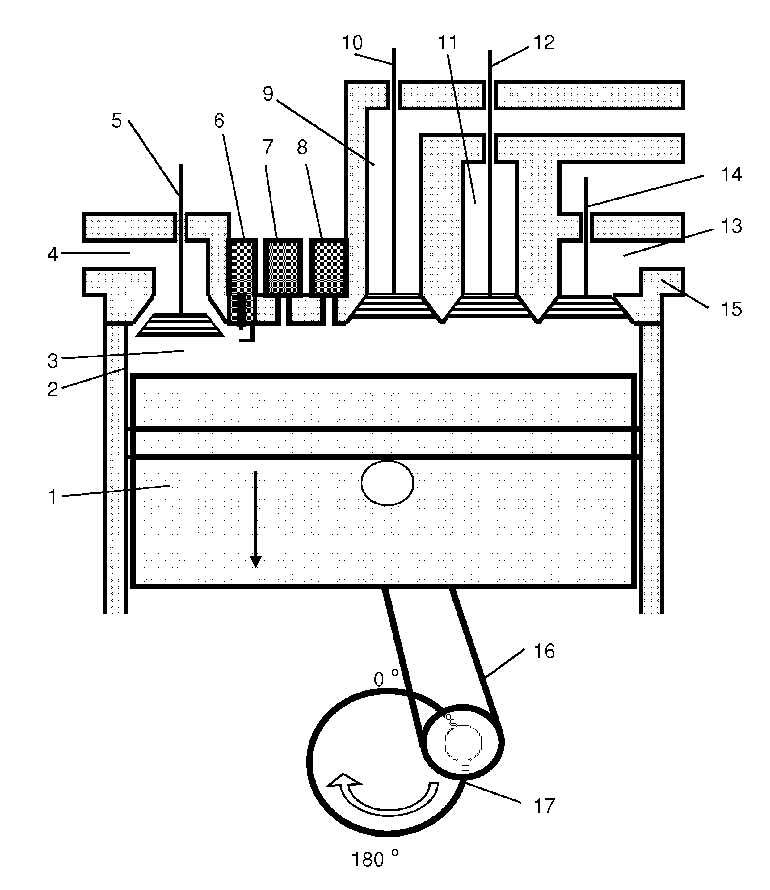
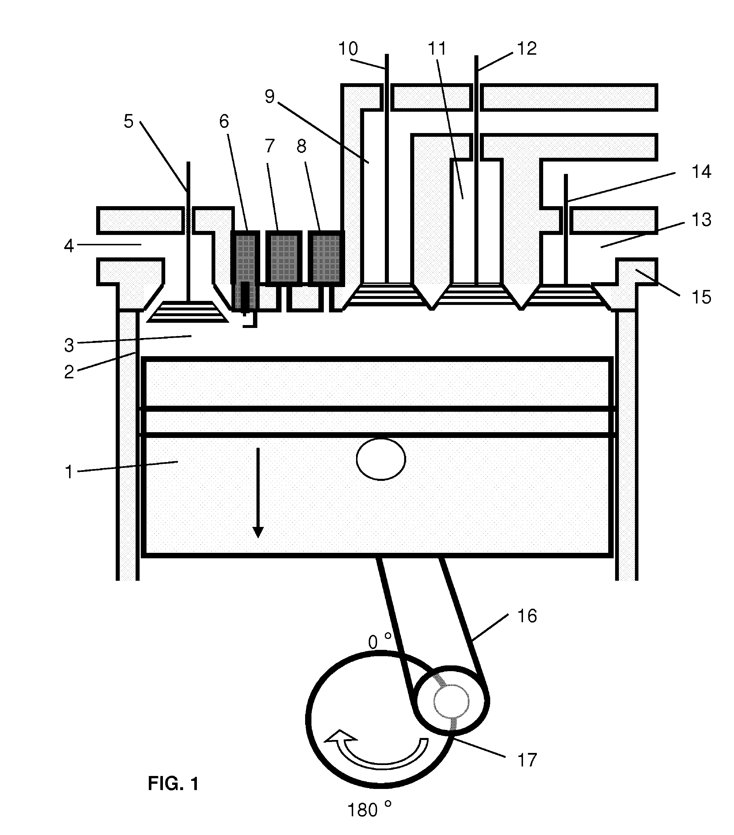
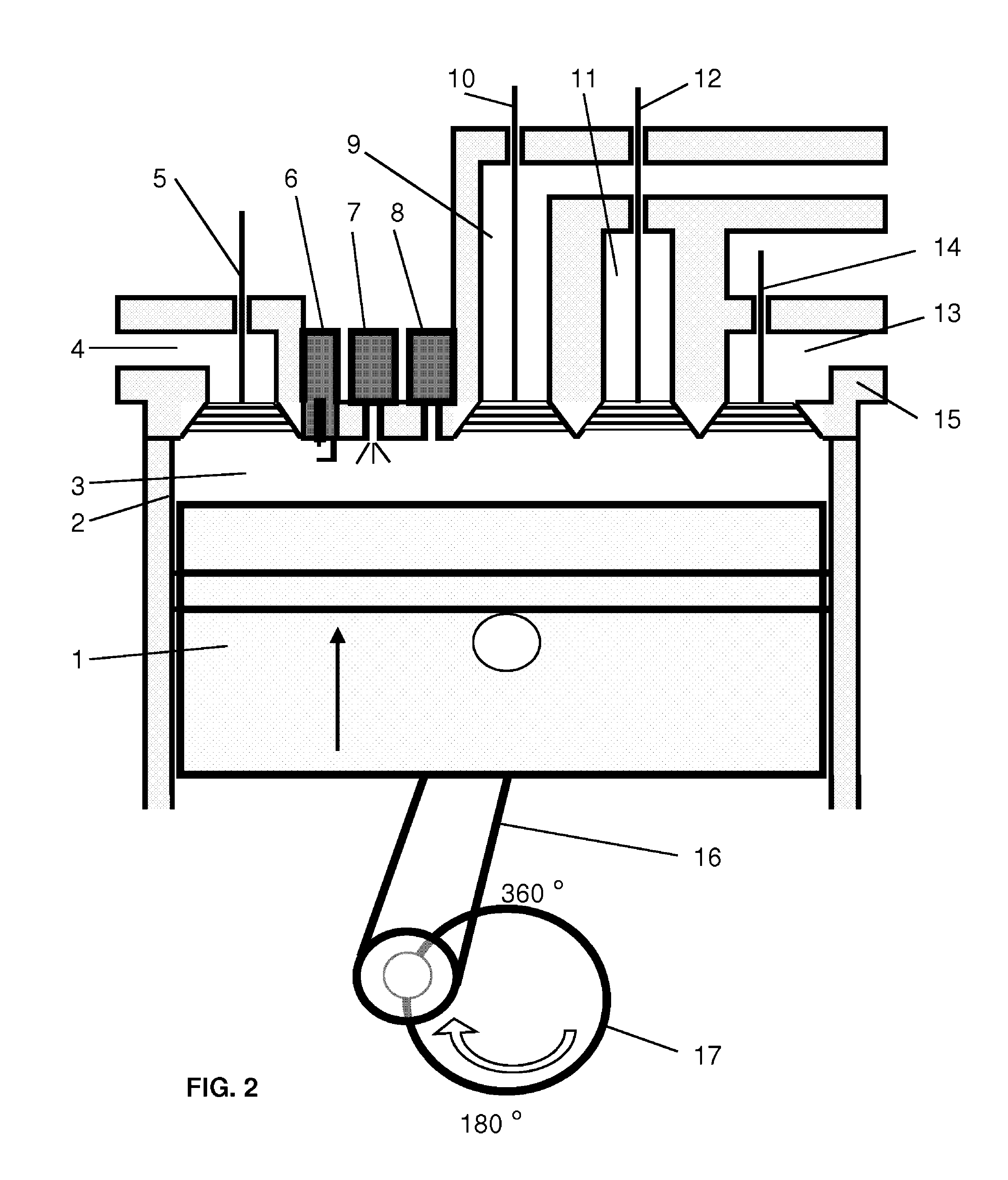
For simplicity in describing this invention, the figures illustrate only one piston inside one cylinder attached to one crankshaft. This invention may use any number of cylinders and pistons as well as multiple crankshafts. The figures are illustrative and are not drawn to scale but schematically depict the method of operating this invention. This engine may be either spark ignited (SI), compression ignited (CI), or utilizing some other means of igniting the combustible mixture. The fuels to be used in this invention include all hydrocarbons as well as hydrogen or mixtures thereof. It is understood that the cylinder 2; the head 15; the connecting conduits 22, 23, 24, 27, 31, 32, 33, 42, and 45; the vaporizer 20 and the steam chest 25; the heat recovery exchanger 30; the pumps 44 and 46; and the hot water reservoir 41 are all insulated to retain heat. This insulation is not shown for clarity on the drawings.

FIG. 1 is a cross sectional view of one piston 1 and cylinder 2 assembly. Thi...


PUM


Abstract

A method and a system for operating an eight-stroke internal combustion engine having higher thermal efficiency than a four-stroke engine is disclosed. The strokes comprise intake (FIG. 1), compression (FIG. 2), combustion for a first power stroke (FIG. 3), exhaust (FIG. 4), vapor or water injection for a second power stroke (FIG. 5), exhaust (FIG. 6), vapor injection for a third power stroke (FIG. 7), and exhaust (FIG. 8). Heat from each exhaust is recovered and recycled to a subsequent stroke. Consequently, an engine with much higher thermal efficiency and thus lower fuel consumption is achieved.

Description

CROSS-REFERENCE TO RELATED APPLICATIONSNot applicableFEDERALLY SPONSORED RESEARCHNot applicableSEQUENCE LISTING OF PROGRAMNot applicableBACKGROUND OF THE INVENTION1. Field of the InventionThe present invention relates to internal combustion engines in general, and more specifically, to engines equipped with heat recovery systems in order to have a higher thermal efficiency than conventional two, four, six, eight, or more stroke internal combustion engines.2. Description of Prior ArtThe internal combustion (IC) engine is well over 100 years old. The original US patent was issued to Nicolaus Otto on Aug. 14, 1877 for a four-stroke spark ignited (SI) engine. An earlier patent was issued to Otto for a four-stroke engine in Germany. A compression ignition (CI) engine, or Diesel engine, was invented a few years after this. Other than rotary engines, which were introduced many years later, internal combustion engines have powered our society and are found almost everywhere. These engines h...

Claims


Application Information

Patent Timeline
Patent Type & Authority Patents(United States)
IPC IPC(8): F02B47/02F01B29/04
CPCF02B47/02F02B75/021F02M25/03F02M25/038Y02T10/121Y02T10/12
Inventor JUNG, PHILIP OWEN
Owner JUNG PHILIP OWEN
Why Eureka
Try Eureka