
Remedial heap treatment

a heap treatment and heap technology, applied in the field of heap leaching materials, can solve the problems of poor infiltration of heap leach fluid into the heap portion, and achieve the effects of effective metal extraction, improved treatment effect, and improved treatment

Active Publication Date: 2011-09-20
NEWMONT USA LTD
View PDF19 Cites 13 Cited by
  • Summary
  • Abstract
  • Description
  • Claims
  • Application Information

AI Technical Summary

Benefits of technology

[0009]In one implementation of the invention, the remedial treatment comprises hydraulically fracturing an identified portion of the heap determined to be deficient in metal extraction, with the hydraulic fracturing followed by direct placement of treating solution into the identified portion of the heap to extract metal. The treating solution is a leach solution for metal to be extracted, and may be the same as leach solution applied to the top of the heap during normal heap leaching operations. In this implementation, the direct placement of the treating solution is accomplished by injecting the treating solution through the well and into the targeted portion of the heap, to displace residual fluids left from the hydraulic fracturing and to saturate the targeted portion of the heap with the treating solution. As a further enhancement, after a reasonable residence time to permit the treating solution to dissolve metal of interest, collection of the treating solution is aided through displacement with a rinse fluid introduced into the heap through the well. Displacement with the rinse solution enhances mobility of the treating solution within the heap and promotes movement of the treating solution through the heap to a collection system where the treating solution can be collected for further processing to recover dissolved metal. In yet a further enhancement, the rinse solution can also be a leach solution for the metal of interest, to thereby dissolve still more metal from the identified portion of the heap. The rinse treatment could then be repeated multiple times at a frequency as appropriate to ensure effective metal extraction from the remedially treated portion of the heap.

Problems solved by technology

A common condition often contributing to deficiency in metal extraction is poor infiltration of heap leach fluids into that portion of the heap, often because of low local permeability, and remedial treatment involves permeability enhancement of a portion of the heap through hydraulic fracture treatment.

Method used


Image

  • Remedial heap treatment
  • Remedial heap treatment
  • Remedial heap treatment

Examples


Embodiment Construction

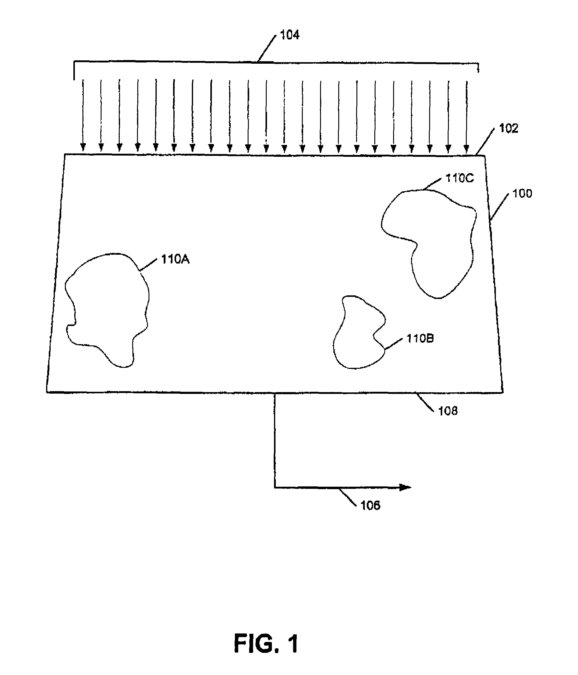
[0019]Figure shows in cross section a heap 100 constructed of particulate gold-bearing mineral material undergoing heap leaching to extract gold, with or without concurrent extraction also of other metal values of interest. Gold is leached from the heap 100 by applying barren feed of leach solution 104, containing a lixiviant for gold, to the top 102 of the heap 100. The leach solution may comprise, for example, cyanide, thiourea, thiosulfate and / or thiocyanate material as lixiviant for gold. The feed 104 of the leach solution may be applied to the top 102 of the heap, for example, by a spray or drip irrigation-type system. The leach solution percolates through the heap 100 and dissolves gold. Pregnant effluent 106 of the leach solution, loaded with dissolved gold, is collected at the base of the heap 108 and is sent to a gold recovery operation to remove the dissolved gold from the pregnant effluent 106 of the leach solution.

[0020]As shown in FIG. 1, there are some portions 110A-C ...


PUM

PropertyMeasurementUnit
particle sizeaaaaaaaaaa
sizeaaaaaaaaaa

Abstract

A system and method are disclosed for improving component extraction from heap leach operations. Following heap leaching for some time, portions of the heap deficient in component extraction are identified, and treatment wells are drilled and remedial treatments are selectively performed on the identified portions of the heap. The remedial treatment can include hydraulically fracturing the identified portions of the heap followed by selective treatment with leach solution of the area impacted by the fracturing.

Description

CROSS-REFERENCE TO RELATED APPLICATION[0001]This application claims a benefit under 35 U.S.C. §119(e) to U.S. Provisional Patent Application No. 60 / 554,695 entitled “REMEDIAL HEAP TREATMENT INVOLVING HYDRAULIC FRACTURING” filed Mar. 19, 2004.FIELD OF THE INVENTION[0002]The present invention relates to heap leaching of materials to extract one or more component of the material; and especially with application to remedial treatment of heaps to improve heap leach extraction of metal values from metal-containing mineral materials.BACKGROUND OF THE INVENTION[0003]One technique for extracting metal from ores and other mineral material is to heap leach the material. An engineered pile, or heap, of particulate material is constructed, typically over an engineered liner and liquid collection system. Leach solution is applied to and percolated through the heap to contact the material and dissolve one or more metal of interest into the leach solution. Pregnant leach solution is collected throu...

Claims


Application Information

Patent Timeline
Patent Type & Authority Patents(United States)
IPC IPC(8): B01D11/02E21B43/28C22B3/12B01F1/00C22B3/04C22B3/06C22B3/08E21B43/26
CPCE21B43/26E21B43/283Y02P10/20
Inventor SEAL, THOMAS JOSEPH
Owner NEWMONT USA LTD
Learn More